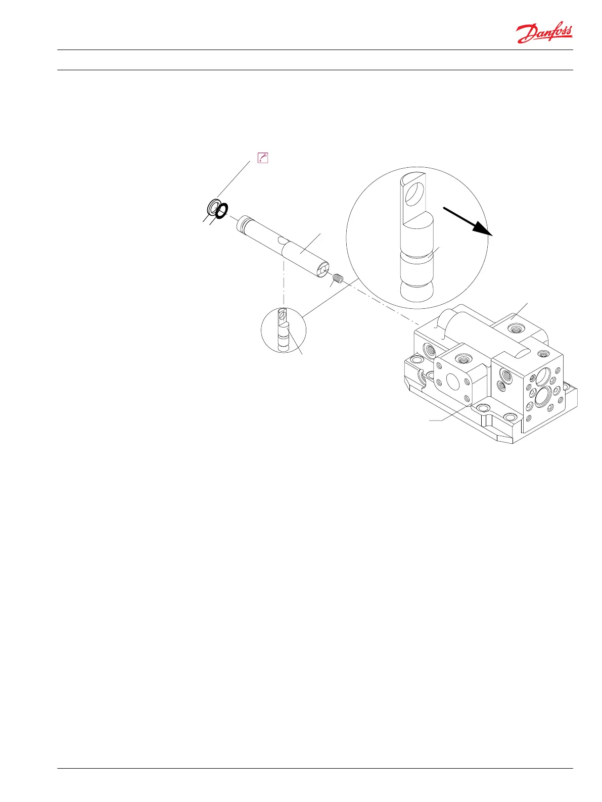
2. Install the cone-point set screw (F26) so that its point enters the groove in the feedback fork (F24) /
setting lug. Do not tighten the set screw yet. See page 21 for final assembly instructions.
Cone-point screw and feedback fork
F24
(110, 160, 250)
End cap (side port style shown)
typical for 110, 160, and 250 frame sizes
G10
F26
F12
Multi-function
block/control
Groove
Lubricate with hydraulic fluid
F10
F11
P104 097
All frame sizes
1. Position feedback fork (F30) (060 cc) or feedback fork/setting lug (080 cc - 250 cc) perpendicular to
the setting piston for proper control spring operation.
2. Insert a 26.9 mm [1.06 in] diameter rod, with the end machined perpendicular to its axis, into the
valve sleeve bore in the end cap. Align the fork while tightening the cone-point set screw (F26).
3. Using a 3 or 5 mm internal hex wrench, torque the cone-point set screw to 5 N•m [44 lbf•in].
4. Install and torque the lock screw (F28) to
•
7 N•m [62 lbf•in] using a 3 mm internal hex wrench for a 60 cc motor
•
34 N•m [25 lbf•ft] using a 5 mm internal hex wrench for the 80 cc through 250 cc motors
Repair Instructions
Series 51 and 51-1 Bent Axis Motors Repair Instructions
Assembly
11009449 • Rev BA • December 2014 21

 Loading...


