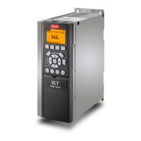
Do you have a question about the Danfoss FC 51 Series and is the answer not in the manual?
General safety instructions and precautions for use.
Precautions to prevent accidental motor starts.
General warnings about electrical hazards and precautions.
Steps to take before performing any repair work.
Overview of programming methods using software or LCP.
Description of the Status Menu and its modes.
Step-by-step guide to using the Quick Menu.
Programming using the MCT 10 software via PC.
Description of the Quick Menu for frequent parameters.
Step-by-step guide to using the Main Menu.
Programming using the Local Control Panel (LCP).
Description of the Main Menu for all parameters.
Parameters for controlling operation and display settings.
Configuration of Local Control Panel (LCP) functions.
Parameters related to motor characteristics and load.
Advanced motor data settings and automatic tuning.
Parameters for configuring various motor start functions.
Settings for monitoring motor temperature.
Parameters related to brake functions.
Parameters for setting speed references and ramps.
Parameters for configuring motor speed, torque, and current limits.
Configuring digital inputs and outputs.
Configuring analog inputs and outputs.
Parameters for configuring application control loops.
Parameters for configuring communication interfaces.
Parameters for configuring Smart Logic Control sequences.
Parameters for special frequency converter functions.
Parameters for managing and selecting different set-ups.
Inputting motor nameplate data for optimal performance.
Parameters for configuring motor stop functions.
Configuration of DC braking functions.
Detailed breakdown of alarm, warning, and status words by bit.
| Enclosure | IP20 |
|---|---|
| Fieldbus communication | CANopen |
| Input Voltage | 200-240V AC, 380-480V AC |
| Output Frequency | 0-400 Hz |
| Protection Features | Overcurrent, overvoltage, undervoltage, short circuit, overtemperature |
| Communication Interfaces | RS-485 |
| Power range | 0.25 kW to 7.5 kW |


