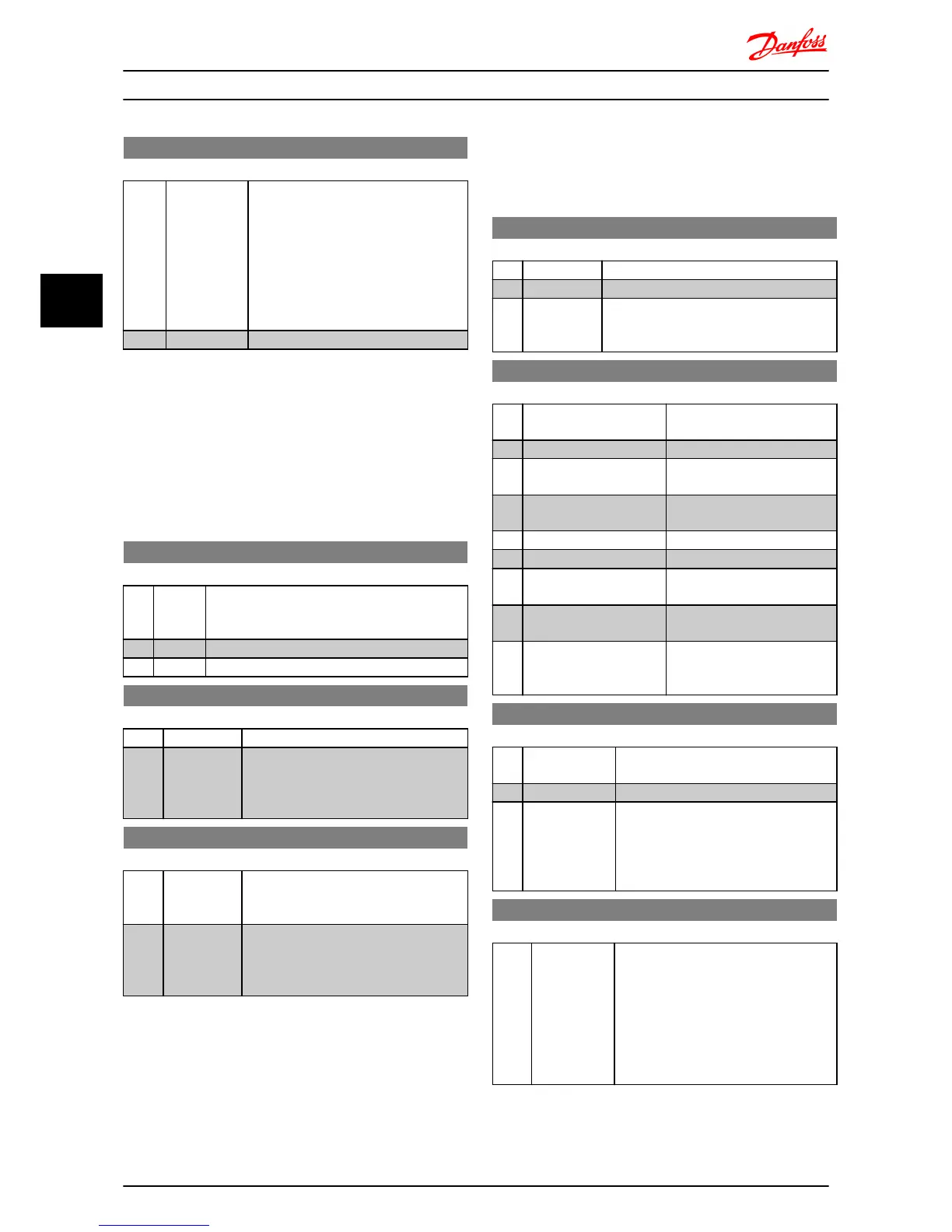
6-26 Terminal 60 Filter Time Constant
Range: Function:
A first-order digital low pass filter time
constant for suppressing electrical noise
in terminal 60. A high time constant
value improves dampening, but also
increases time delay through the filter.
NOTE
This parameter cannot be changed
while motor runs.
0.01 s* [0.01-10.00 s] Enter time constant.
4.7.5 6-8* LCP Potentiometer
The LCP potentiometer can be selected either as Reference
Resource or Relative Reference Resource.
NOTE
In Hand mode the LCP potentiometer functions as local
reference.
6-80 LCP Potmeter Enable
Option: Function:
If LCP Potmeter is disabled, [▲] [▼] can adjust
local reference, and Potmeter value does not give
any reference in Auto/Hand mode.
[0] Disabled
[1] * Enable
6-81 LCP Potentiometer Low Ref. Value
Range: Function:
The scaling value corresponding to 0.
0.000* [-4999-4999] Enter low reference value.
The reference value corresponding to
potentiometer turned fully counter-
clockwise (0 degrees).
6-82 LCP Potentiometer High Ref. Value
Range: Function:
The scaling value corresponding to the
maximum reference feedback value set in
3-03 Maximum Reference.
50.00* [-4999-4999] Enter high reference value.
The reference value corresponding to
potentiometer turned fully clockwise (200
degrees).
4.7.6 6-9* Analog Output
These parameters are for configuring the analog outputs of
the frequency converter.
6-90 Terminal 42 Mode
Option: Function:
[0] * 0-20 mA Range for analog outputs is 0-20 mA
[1] 4-20 mA Range for analog outputs is 4-20 mA
[2] Digital output Functions as slow reacting digital output.
Set value to either 0 mA (off) or 20 mA (on),
see 6-92 Terminal 42 Digital Output.
6-91 Terminal 42 Analog Output
Option: Function:
Select the function for terminal
42 as an analog output.
[0] * No Operation
[10] Output Frequency [0-100
Hz]
[11] Reference (REF min-max)
3-02 Minimum Reference to 3-03
Minimum Reference.
[12] Feedback (FB min-max)
[13] Motor Current (0-I
max
)
16-37 Inv. Max. Current is I
max
.
[16] Power (0-P
nom
)
1-20 Motor Power is P
nom
(motor).
[19] DC Link Voltage (0-1000
V)
[20] Bus Reference [0.0%
-100.0%]
The analog output will follow
the reference value set on the
RS-485 bus.
6-92 Terminal 42 Digital Output
Option: Function:
See parameter group 5-4* Relays, for
choices and descriptions.
[0] * No Operation
[80] SL Digital
Output A
See 13-52 SL Control Action. When Smart
Logic Action [38] Set dig. out. A high is
executed, input goes high. When Smart
Logic Action [32] Set dig. out. A low is
executed, input goes low.
6-93 Terminal 42 Output Min. Scale
Range: Function:
0.00% [0.00-200.0%] Scale minimum output of selected analog
signal at terminal 42 as percentage of
maximum signal value. E.g. if 0 mA (or 0
Hz) is desired at 25% of maximum output
value, program 25%. Scaling values up to
100% can never be higher than
corresponding setting in 6-94 Terminal 42
Output Min. Scale.
Parameter Descriptions
VLT
®
Micro Drive FC 51 Programming Guide
34 MG02C602 - VLT
®
is a registered Danfoss trademark
44

 Loading...


