4.2 Parameter Group 1: Load/Motor
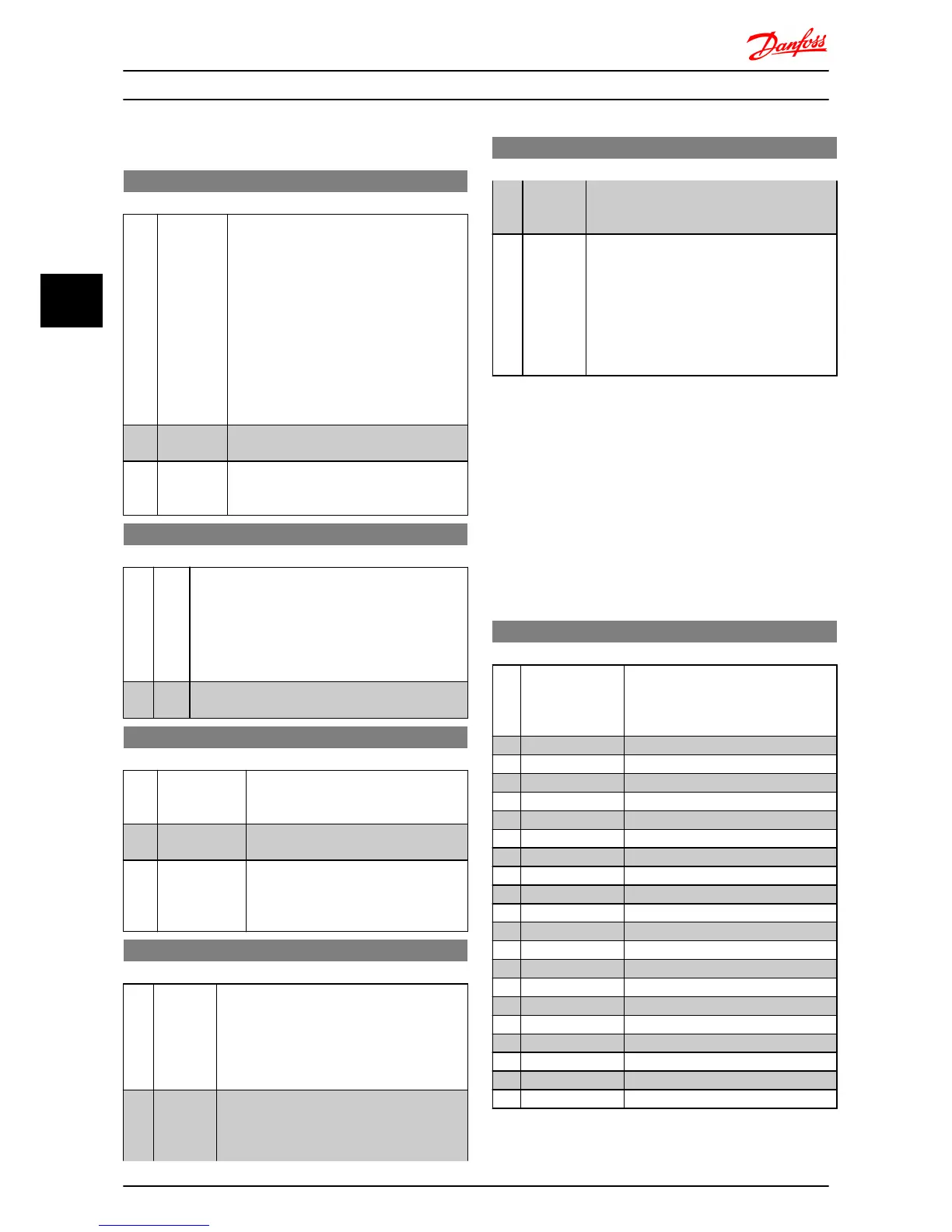
1-00 Configuration Mode
Option: Function:
Use this parameter for selecting the
application control principle to be used when
a Remote Reference is active.
NOTE
Changing this parameter will reset 3-00
Reference Range, 3-02 Minimum Reference
and 3-03 Maximum Reference to their
default values.
NOTE
This parameter cannot be adjusted
while motor runs.
[0 ] * Speed
Open Loop
For normal speed control (References).
[3] Process
Closed
Loop
Enables process closed loop control. See
parameter group 7-3* Process PI Control for
further information on PI-controller.
1-01 Motor Control Principle
Option: Function:
[0] U/f Is used for parallel connected motors and/or special
motor applications. The U/f settings are set in 1-55
U/f Characteristic -U and 1-56 U/f Characteristic -F.
NOTE
When running U/f control slip- and load
compensations are not included.
[1] * VVC+ Normal running mode, including slip- and load
compensations.
1-03 Torque Characteristics
Option: Function:
With more torque characteristics it is
possible to run low energy consuming, as
well as high torque applications.
[0 ] * Constant
Torque
Motor shaft output provides constant
torque under variable speed control.
[2] Automatic
Energy Optimi-
sation
This function automatically optimizes
energy consumption in centrifugal pump
and fan applications. See 14-41 AEO
Minimum Magnetisation.
1-05 Hand Mode Configuration
Option: Function:
This parameter is only relevant when 1-00
Configuration Mode is set to [3] Process Closed
Loop. The parameter is used for determining
the reference or setpoint handling when
changing from Auto Mode to Hand Mode on
the LCP.
[0] Speed
Open
Loop
In Hand Mode the drive always runs in Open
Loop configuration regardless of setting in 1-00
Configuration Mode. Local potentiometer (if
present) or Arrow up/down determines output
1-05 Hand Mode Configuration
Option: Function:
frequency limited by Motor Speed High/Low
Limit (4-14 Motor Speed High Limit and 4-12
Motor Speed Low Limit).
[2] * As config-
uration in
1-00
Configu-
ration
Mode.
If 1-00 Configuration Mode is set to [1] Open
Loop function is as described above.
If 1-00 Configuration Mode is set to [3] Process
Closed Loop changing from Auto mode to Hand
mode results in a setpoint change via local
potentiometer or Arrow up/down. The change
is limited by Reference Max/Min (3-02 Minimum
Reference and 3-03 Maximum Reference).
4.2.1 1-2* Motor Data
Enter the correct motor nameplate data (power, voltage,
frequency, current and speed).
Run AMT, see 1-29 Automatic Motor Tuning (AMT).
Factory settings for advanced motor data, parameter group
1-3* Adv. Motor Data, are automatically calculated.
NOTE
Parameters in parameter group 1-2* Motor Data cannot be
adjusted while motor runs.
1-20 Motor Power [kW]/[HP] (P
m.n
)
Option: Function:
Enter motor power from nameplate
data.
Two sizes down, one size up from
nominal VLT rating.
[1] 0.09 kW/0.12 HP
[2] 0.12 kW/0.16 HP
[3] 0.18kW/0.25 HP
[4] 0.25 kW/0.33 HP
[5] 0.37kW/0.50 HP
[6] 0.55 kW/0.75 HP
[7] 0.75 kW/1.00 HP
[8] 1.10 kW/1.50 HP
[9] 1.50 kW/2.00 HP
[10] 2.20 kW/3.00 HP
[11] 3.00 kW/4.00 HP
[12] 3.70 kW/5.00 HP
[13] 4.00 kW/5.40 HP
[14] 5.50 kW/7.50 HP
[15] 7.50 kW/10.0 HP
[16] 11.00 kW/15.00 HP
[17] 15.00 kW/20.00 HP
[18] 18.50 kW/25.00 HP
[19] 22.00 kW/29.50 HP
[20] 30.00 kW/40.00 HP
Parameter Descriptions
VLT
®
Micro Drive FC 51 Programming Guide
14 MG02C602 - VLT
®
is a registered Danfoss trademark
44

 Loading...


