4.2.7 1-9* Motor Temperature
With an estimated motor temperature monitor the
frequency converter is able to estimate motor temperature
without having a thermistor mounted. It is thus possible to
receive a warning or an alarm, if motor temperature
exceeds upper operational limit.
1-90 Motor Thermal Protection
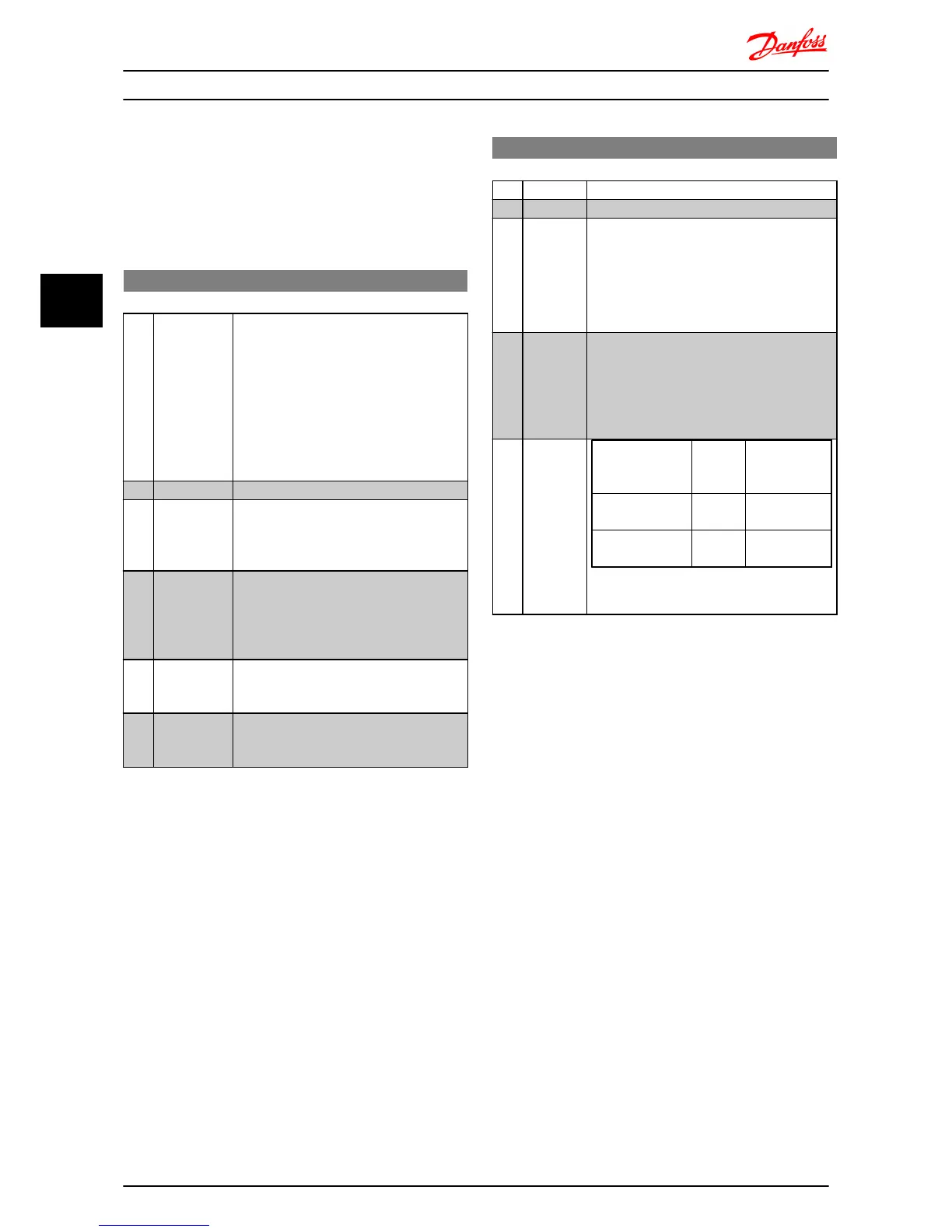
Option: Function:
Using ETR (Electronic Terminal Relay) the
motor temperature is calculated based on
frequency, speed and time. Danfoss
recommends using The ETR function, if a
thermistor is not present.
NOTE
ETRElectronic Overload calculation is
based on motor data from parameter
group 1-2* Motor Data.
[0] * No Protection Disables temperature monitoring.
[1] Thermistor
Warning
A thermistor connected to either digital or
analog input gives a warning if upper limit
of motor temperature range is exceeded,
(see 1-93 Thermistor Resource).
[2] Thermistor
Trip
A thermistor connected to either digital or
analog input gives an alarm and makes the
frequency converter trip if upper limit of
motor temperature range is exceeded, (see
1-93 Thermistor Resource.
[3] ETR Warning If calculated upper limit of motor
temperature range is exceeded, a warning
occurs.
[4] ETR Trip If 90% of calculated upper limit of motor
temperature range is exceeded, an alarm
occurs and the frequency converter trips.
NOTE
When the ETR function has been selected the drive will
store the recorded temperature at power down and this
temperature will resume at power up regardless of the
elapsed time. Changing 1-90 Motor Thermal Protection back
to [0] No Protection will reset the recorded temperature.
1-93 Thermistor Resource
Option: Function:
Select the thermistor input terminal.
[0] * None No thermistor is connected.
[1] Analog
Input 53
Connect thermistor to analog input terminal
53.
NOTE
Analog input 53 cannot be selected for
other purposes when selected as
thermistor resource.
[6] Digital
input 29
Connect thermistor to digital input terminal 29.
While this input functions as thermistor input,
it will not respond to the function chosen in
5-13 Digital Input 29. The value of 5-13 Digital
Input 29 remains however unchanged in
parameter database while function is inactive.
Input Digital/
Analog
Supply
Voltage
Threshold Cut-
out
Values
Digital 10 V
<800 Ω ⇒ 2.9
kohm
Analog 10 V
<800 Ω ⇒ 2.9
kohm
Table 4.1
Parameter Descriptions
VLT
®
Micro Drive FC 51 Programming Guide
18 MG02C602 - VLT
®
is a registered Danfoss trademark
44

 Loading...


