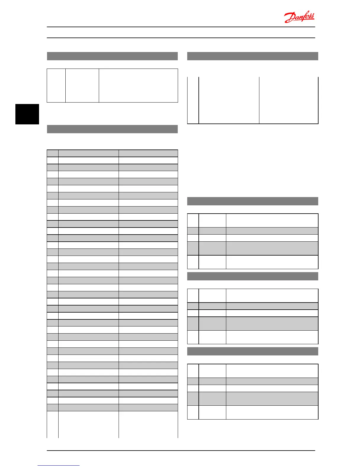
8-36 Max Response Delay
Range: Function:
5.000 s* [0.010-10.00 s] Specify maximum permissible delay
time between transmitting a request
and receiving a response. Exceeding
this time delay causes control word
timeout.
4.9.4 8-4* FC MC Protocol Set
8-43 FC Port PCD Read Configuration
Array [16]
Option: Function:
[0] * None
[1] 1500 Operation Hours
[2] 1501 Running Hours
[3] 1502 kWh Counter
[4] 1600 Control Word
[5] 1601 Reference [Unit]
[6] 1602 Reference %
[7] 1603 Status Word
[8] 1605 Main Actual Value [%]
[9] 1609 Custom Readout
[10] 1610 Power [kW]
[11] 1611 Power [hp]
[12] 1612 Motor Voltage
[13] 1613 Frequency
[14] 1614 Motor Current
[15] 1615 Frequency [%]
[16] 1618 Motor Thermal
[17] 1630 DC Link Voltage
[18] 1634 Heatsink Temp.
[19] 1635 Inverter Thermal
[20] 1638 SL Controller State
[21] 1650 External Reference
[22] 1651 Pulse Reference
[23] 1652 Feedback [Unit]
[24] 1660 Digital Input 18,19,27,33
[25] 1661 Digtial Input 29
[26] 1662 Analog Input 53(V)
[27] 1663 Analog Input 53(mA)
[28] 1664 Analog Input 60
[29] 1665 Analog Output 42 [mA]
[30] 1668 Freq. Input 33 [Hz]
[31] 1671 Relay Output [bin]
[32] 1672 Counter A
[33] 1673 Counter B
[34] 1690 Alarm Word
[35] 1692 Warning Word
[36] 1694 Ext. Status Word
Select the parameters to be
assigned to PCD's of
telegrams. The number of
available PCDs depends on
8-43 FC Port PCD Read Configuration
Array [16]
Option: Function:
the telegrams. This table is
not for [0] array and [1]
array . For these two arrays,
index 1 is fixed to [7] and
index 2 is fixed to [8]. These
two arrays cannot be
changed by end user.
4.9.5 8-5* Digital/Bus
Parameters for configuring control word Digital/Bus
merging.
NOTE
Parameters are only active when 8-01 Control Site, is set to
[0] Digital and control word.
8-50 Coasting Select
Option: Function:
Select control of coasting function via digital
input and/or bus.
[0] Digital Input Activation via a digital input.
[1] Bus Activation via serial communication port.
[2] LogicAnd Activation via serial communication port and
a digital input.
[3] * LogicOr Activation via serial communication port or a
digital input.
8-51 Quick Stop Select
Option: Function:
Select control of quick stop function via
digital input and/or bus.
[0] Digital Input Activation via a digital input.
[1] Bus Activation via serial communication port.
[2] LogicAnd Activation via serial communication port and
a digital input.
[3] * LogicOr Activation via serial communication port or a
digital input.
8-52 DC Brake Select
Option: Function:
Select control of DC brake via digital input
and/or bus.
[0] Digital Input Activation via a digital input.
[1] Bus Activation via serial communication port.
[2] LogicAnd Activation via serial communication port and
a digital input.
[3] * LogicOr Activation via serial communication port or a
digital input.
Parameter Descriptions
VLT
®
Micro Drive FC 51 Programming Guide
38 MG02C602 - VLT
®
is a registered Danfoss trademark
44