4. Tighten the screws by hand in a double-X pattern while rotating the motor shaft to ensure proper
positioning of the synchronizing shaft rollers.
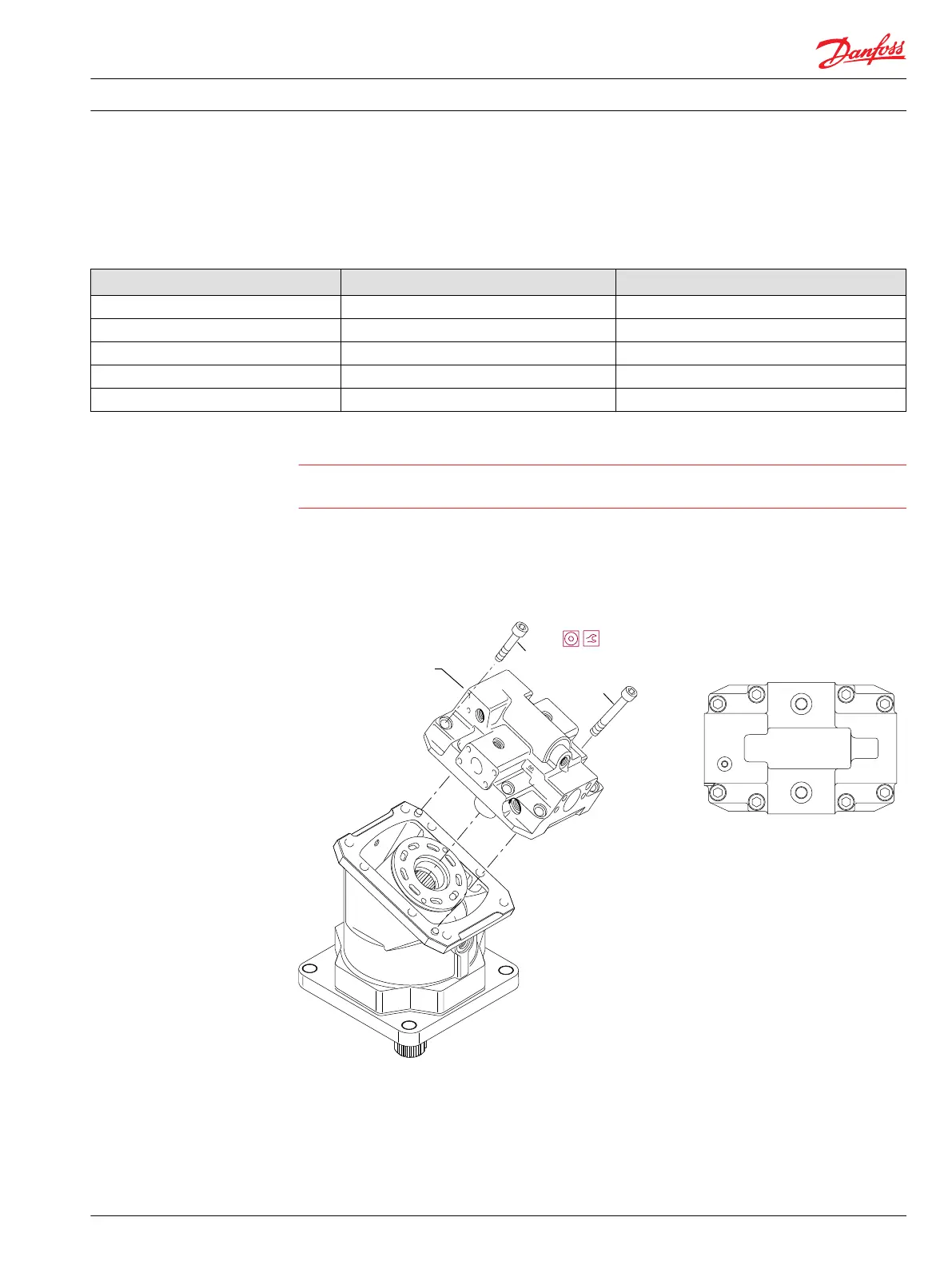
5. When the end cap is in position, torque the screws in a double-X pattern as shown in the table:
Endcap screw torque
Frame size Wrench size Torque N•m [lbf•ft]
060 8 mm 66 [49]
080 8 mm 78 [58]
110 10 mm 115 [85]
160 10 mm 135 [100
250 12 mm 213 [157]
Caution
Do not force the end cap into position on the housing. If necessary, reassemble the components to
ensure proper alignment.
6. Recheck the end cap screw torque.
7. Reinstall the minimum angle servo cover, control springs (if used), 4-way valve spool and sleeve (if
used), and control and multifunction block (if used). Refer to Series 51 and 51-1 Service Manual,
11008567 for instructions.
Torquing pattern
G34
SAE flange version shown
cartridge version similar
G32
Endcap assembly
with valve segment
Double-X pattern torquing sequence
(110 frame size with side port end cap shown)
3/11
7/15
P104 106
2/10
5/13
6/14
1/9
4/12
8/16
see table
Following procedures in the Series 51 and 51-1 Service Manual, 11008567: Install the control and
multi-function block (if installed). Install the 4-way valve spool and sleeve (if installed). Install the
threshold springs and guides. Install the control springs (if installed). Install the ramp springs and
guides (if installed). Install the minimum angle servo cover from the motor. Install the loop-flushing
valve and charge relief valve.
Repair Instructions
Series 51 and 51-1 Bent Axis Motors Repair Instructions
Assembly
11009449 • Rev BA • December 2014 31

 Loading...


