Non-linear manual displacement control (MDC)
A centering spring, located on the control input shaft, locates the control shaft in its neutral position. A
bias spring on the control spool maintains a force on the spool and the control linkage to eliminate free-
play in the linkage.
Neutral adjustment is the only adjustment that can be made on the nonlinear manual displacement
control. All other functions are preset at the factory. Perform neutral adjustment on a test stand or on the
vehicle/machine with the prime mover operating.
Warning
Unintended movement of the machine or mechanism may cause injury to the technician or bystanders.
To protect against unintended movement, secure the machine or disable/disconnect the mechanism
while servicing.
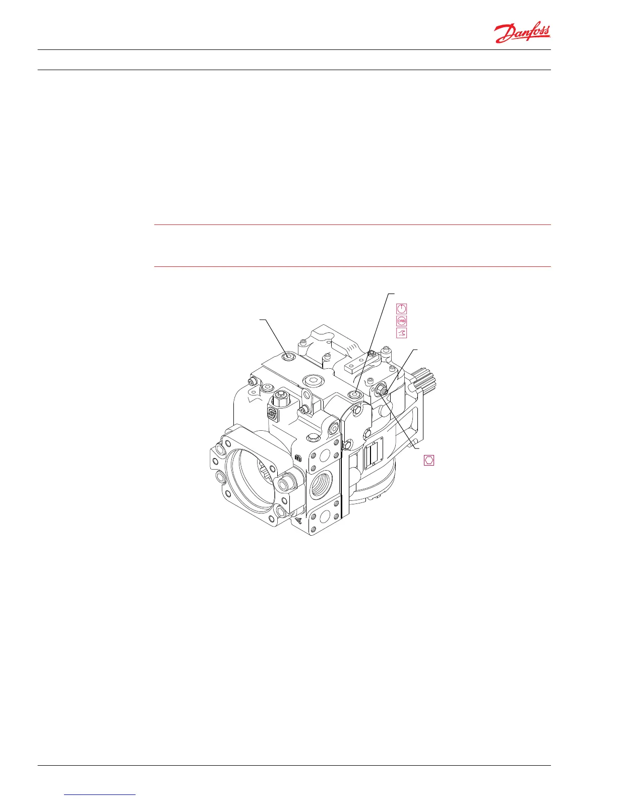
MDC neutral adjustment
Servo pressure gauge port M4
Servo pressure gauge port M5
G
B
t
0 - 50 bar [0 - 1000 psi]
9/16-18
12 N•m [9 lbf•ft]
0 - 50 bar [0 - 1000 psi]
9/16-18
12 N•m [9 lbf•ft]
P106 165E
13 mm
13 N•m [10 lbf•ft]
I4 mm
M90
M72
1. Install a 50 bar [1000 psi] gauge in each of the two servo cylinder gauge ports (M4 and M5).
Disconnect the external control linkage from the control handle and make certain the control shaft is
in its neutral position. Start the prime mover and operate at normal speed.
2. Loosen the lock nut (M90) on the neutral adjusting screw (M72) with a 13 mm hex wrench.
3. Using a 4 mm internal hex wrench, rotate the neutral adjusting screw clockwise until the pressure
increases on one of the pressure gauges. Note the angular position of the wrench. Then rotate the
adjusting screw counterclockwise until the pressure increases by an equal amount on the other
gauge. Note the angular position of the wrench.
4. Rotate the adjusting screw clockwise half the distance between the locations noted above. The
gauges should read the same pressure, indicating that the control is in its neutral position.
5. Hold the adjusting screw stationary and tighten the lock nut to 13.5 N•m [10 lbf•ft]. Do not overtorque
the nut.
6. Once the neutral position is set, stop the prime mover, remove the gauges, and install the gauge port
plugs. Reconnect the external control linkage.
Service Manual
Series 90 Pumps
Adjustments
34 520L0818 • Rev 0101 • August 2015