Warning
The following procedure may require the vehicle/machine to be disabled (wheels raised off the ground,
work function disconnected, etc.) while performing the procedure in order to prevent injury to the
technician and bystanders. Take necessary safety precautions before moving the vehicle/machine.
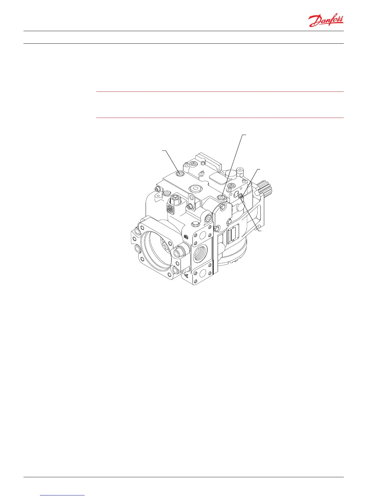
HDC and EDC neutral adjustment
Servo pressure gauge port M4
Servo pressure gauge port M5
G
B
t
G
B
t
0 - 50 bar [0 - 1000 psi]
9/16-20
12 N•m [9 lbf•ft]
0 - 50 bar [0 - 1000 psi]
9/16-20
12 N•m [9 lbf•ft]
P106 167E
10 or 13 mm
7 N•m [5 lbf•ft] or
13 N•m [10 lbf•ft]
I 3 or 4 mm
M90
M72
t
h
1. Install a 50 bar [1000 psi] gauge in each of the two displacement control cylinder gauge ports (M4
and M5). Disconnect the external control input (hydraulic or electronic) from the control. Start the
prime mover and operate at normal speed.
2. Loosen the lock nut (M90) with a 10 mm or 13 mm hex wrench.
3. Using a 3 mm or 4 mm internal hex wrench, rotate the adjusting screw (M72) clockwise until the
pressure increases in one of the pressure gauges. Note the angular position of the wrench. Rotate the
neutral adjusting screw counterclockwise until the pressure increases by an equal amount on the
other gauge. Again note the angular position of the wrench.
4. Rotate the adjusting screw clockwise half the distance between the locations noted above. The
gauges should read the same pressure (case pressure), indicating that the control is in its neutral
position.
5. Hold the neutral adjusting screw stationary. Tighten the neutral adjusting screw lock nut to 7 N•m [62
lbf•in] for the 6 mm screw or 13.5 N•m [120 lbf•in] for the 8 mm screw. Do not overtorque the nut.
6. Once the neutral position is set, stop the prime mover, remove the gauges, and install the gauge port
plugs. Reconnect the external control input.
Speed sensor adjustment
When installing or adjusting the speed sensor on a pump, it must be set at a specific distance from the
speed ring on the unit’s cylinder. To locate the position of the speed sensor on the unit or description see
the corresponding section.
1. Loosen the sensor lock nut with an 11/16 inch hex wrench.
2. Turn the sensor clockwise (CW) by hand until it contacts the speed ring.
Service Manual
Series 90 Pumps
Adjustments
40 520L0818 • Rev 0101 • August 2015