EasyManuals Logo
Home>Danfoss>Water Pump>90 Series

Danfoss 90 Series Service Manual

Danfoss 90 Series
72 pages
To Next Page IconTo Next Page
To Previous Page IconTo Previous Page
Page #41 background imageLoading...
Page #41 background image
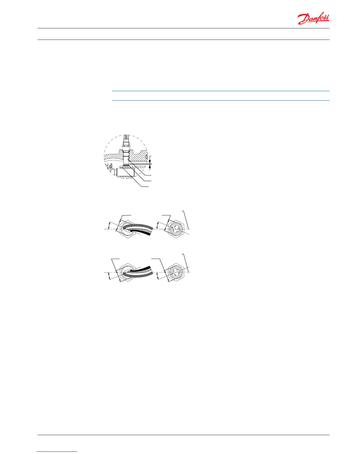
3. Turn the sensor counterclockwise (CCW) 1/2 turn (180°) to establish the nominal gap of 0.71 mm
[0.028 inch].
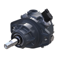
4. Then turn the sensor clockwise (CW) until the wrench flats on sensor body are positioned at a 22°
angle to the pump shaft center line.
Most open-end wrenches have a 22° handle offset.
5. The final sensor position should be between 1/2 (180°) and 1/4 turn (90°) counterclockwise (CCW)
from the point where the sensor contacts the speed ring.
6. Hold sensor in position with a 1/2 inch hex wrench while tightening the lock nut to 13 N•m [10 lbf•ft].
Cross section view of speed sensor in variable pump
Magnetic speed ring
Speed sensor
Gap
P104 152E
Cylinder block
Positioning speed sensor relative to pump shaft
1/2 inch wrench flats
22°
Speed sensor with
packard connector
22°
Speed sensor with
turck connector
1/2 inch wrench flats
22°
Speed sensor with
packard connector
22°
Speed sensor with
turck connector
Shaft centerline
Shaft centerline
P104 155E
Service Manual Series 90 Pumps
Adjustments
520L0818 • Rev 0101August 2015 41

Table of Contents

Other manuals for Danfoss 90 Series

Questions and Answers:

Question and Answer IconNeed help?

Do you have a question about the Danfoss 90 Series and is the answer not in the manual?

Danfoss 90 Series Specifications

General IconGeneral
BrandDanfoss
Model90 Series
CategoryWater Pump
LanguageEnglish

Related product manuals