1. Install the inner port plate (H31) and the gerotor assembly outer ring.
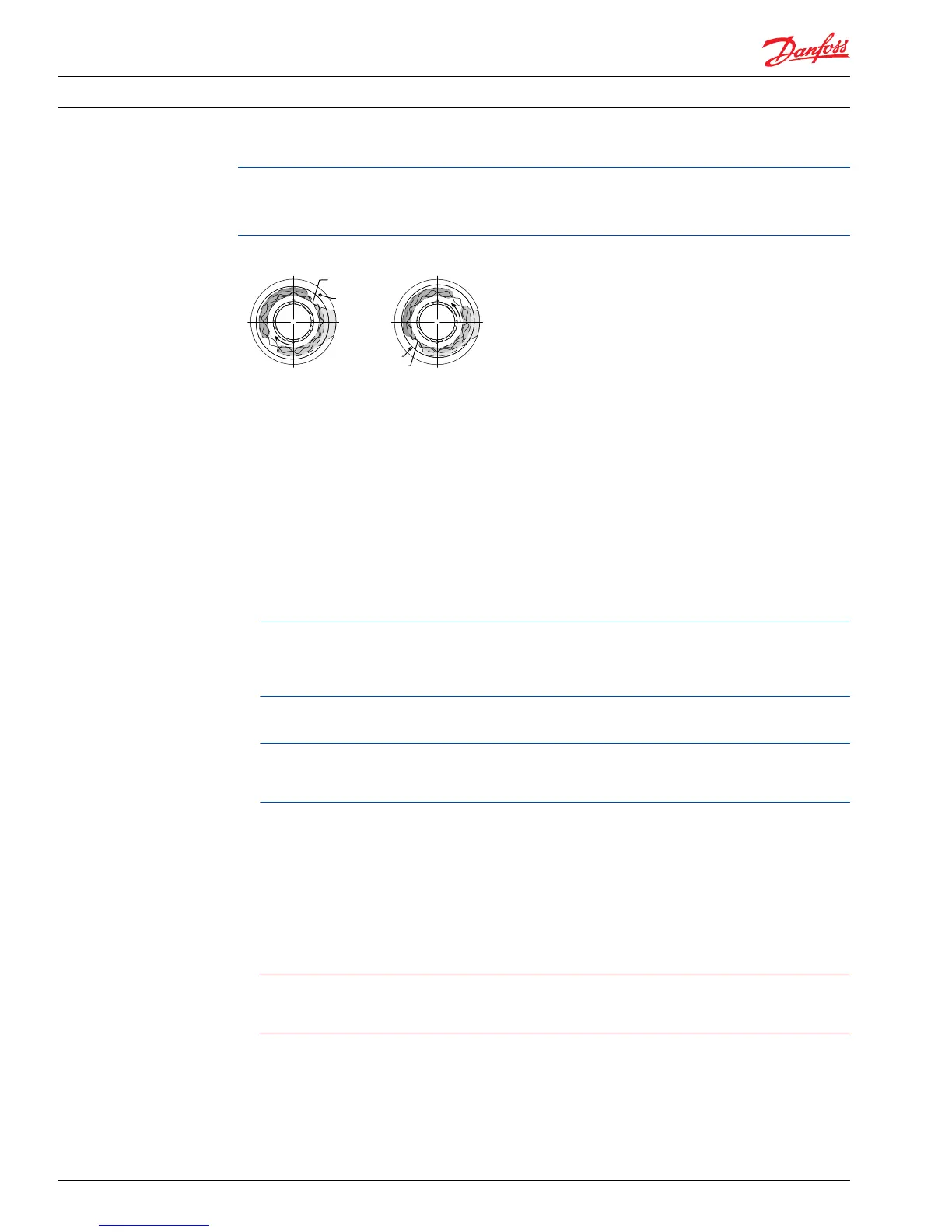
2. Install the alignment pin (H40) to properly orient the port plates and outer eccentric ring for
corresponding pump rotation.
3. Prior to installation, lubricate the I.D., O.D., and side faces of the gerotor assembly.
4. Install the gerotor assembly (H05).
5. Install the outer port plate (early production and intermediate production pumps only).
6. Install the spacer plate, if present (intermediate production pumps).
7. Install the charge pump drive key (H60) into the charge pump coupling (H50) and retain with
petroleum jelly.
Intermediate production 75 cm³ and 100 cm³ pumps use the same charge pump coupling. Two
keyways are provided in the coupling for the charge pumps used in these units. The rear keyway
(with identifier groove) is used in 75 cm³ pumps. The front keyway (closest to the internally splined
end of the shaft) is used in 100 cm³ pumps.
8. Install the charge pump coupling. The internally splined end of the coupling must engage the main
pump shaft.
The outside diameter of the internally splined end of some early production charge pump couplings
were chamfered. Early production end caps may not be machined to accept a non-chamfered
coupling. Always use a chamfered charge pump coupling in pumps with the early endcap.
9. For pumps with an auxiliary mounting pad, install the auxiliary drive coupling.
10. For pumps with no auxiliary pad, install a new O-ring (J40) onto charge pump cover. (If an auxiliary
pad is installed, an O-ring is not used on the cover.)
11. Carefully remove the alignment pin from the charge pump parts. Install the pin in its hole in the
charge pump cover (J15) (see previous page for correct orientation) and retain with petroleum jelly.
Install the cover (with alignment pin) into the end cap and aligned charge pump parts. (Take care not
to damage the cover O-ring, if used.)
Caution
In order to avoid loss of charge pressure in pumps with an auxiliary mounting pad, always install the
charge pump cover with the pad drain hole located on the same side of the end cap as the charge
inlet port. Refer to the section “Auxiliary Pad Installation” for details.
Service Manual
Series 90 Pumps
Minor repair
54 520L0818 • Rev 0101 • August 2015