EasyManua.ls Logo

Danfoss ADAP-KOOL AKD 102 User Manual

Danfoss ADAP-KOOL AKD 102
143 pages
To Next Page IconTo Next Page
Page #1 background imageLoading...
Page #1 background image
Contents
1 How to Read these Operating Instructions
5
Copyright, limitation of liability and revision rights 5
2 Safety
7
High voltage warning 7
Safety Instructions 7
General Warning 7
Before commencing repair work 8
Special conditions 8
Avoid unintended start 9
Safe Stop of the frequency converter 9
IT mains 11
3 Mechanical Installation
13
How to Get Started 13
Pre-installation 13
Planning the Installation Site 13
Receiving the Frequency Converter 14
Transportation and Unpacking 14
Lifting 15
Mechanical Dimensions 16
Rated Power 18
Mechanical Installation 19
Terminal Locations - Frame size D 21
Cooling and Airflow 23
Field Installation of Options 28
Installation of Duct Cooling Kit in Rittal Enclosures 28
Outside Installation/ NEMA 3R Kit for Rittal Enclosures 29
Installation on Pedestal 30
Installation of Input Plate Options 30
Installation of Mains Shield for Frequency Converters 31
4 Electrical Installation
33
Electrical Installation 33
Power Connections 33
Mains Connection 40
Fuses 41
Motor Insulation 42
Motor Bearing Currents 42
Control Cable Routing 43
Electrical Installation, Control Terminals 44
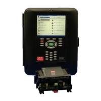
ADAP-KOOL
®
Drive AKD 102 High Power Contents
MG.11.O1.02 - ADAP-KOOL
®
is a registered Danfoss trademark
1

Table of Contents

Questions and Answers:

Danfoss ADAP-KOOL AKD 102 Specifications

General IconGeneral
TypeController
Supply Voltage24 V AC/DC
Number of Analog Inputs2
Output TypeRelay
Power Consumption5 W
Protection ClassIP20
Housing MaterialPlastic
Storage Temperature-40°C to +70°C
Communication ProtocolModbus RTU
Input TypeDigital/Analog
Relative HumidityMax. 95% RH, non-condensing

Summary

How to Read Operating Instructions

Copyright, limitation of liability and revision rights

Details copyright, liability limitations, and revision rights for the manual.

Symbols

Explains the meaning of symbols used throughout the manual for warnings and notes.

Safety

High voltage warning

Warns about the dangers of high voltage from the frequency converter and option card.

Safety Instructions

Provides essential safety instructions and precautions before operating or servicing the unit.

General Warning

Highlights general warnings regarding electrical hazards and necessary waiting times after power disconnection.

Mechanical Installation

3.1 How to Get Started

Outlines the initial steps and overview for mechanical and electrical installation.

3.2 Pre-installation

Covers planning and preparation steps before the actual installation begins.

3.2.1 Planning the Installation Site

Emphasizes the importance of planning the installation site for the frequency converter.

3.2.2 Receiving the Frequency Converter

Provides guidelines for checking the unit upon receipt and reporting any transit damage.

3.2.3 Transportation and Unpacking

Offers recommendations for safely transporting and unpacking the frequency converter unit.

3.2.4 Lifting

Details the correct methods and precautions for lifting the frequency converter unit.

3.2.5 Mechanical Dimensions

Presents detailed mechanical dimensions for various frame sizes of the frequency converter.

3.2.6 Rated Power

Lists the rated power specifications for different frame sizes and enclosure types.

3.3 Mechanical Installation

Covers tools needed and general considerations for the mechanical installation process.

3.3.1 Tools Needed

Lists the necessary tools required to perform the mechanical installation of the unit.

3.3.2 General Considerations

Discusses important general considerations like space and wire access for installation.

3.3.3 Terminal Locations - Frame size D

Shows terminal positions for frame size D, aiding in cable access planning.

3.3.4 Cooling and Airflow

Explains different cooling methods and airflow requirements for the unit.

3.3.5 Installation on the Wall - IP21 (NEMA 1) and IP54 (NEMA 12) Units

Details the procedure for mounting the unit on a wall for specific enclosure types.

3.3.6 Gland/Conduit Entry - IP21 (NEMA 1) and IP54 (NEMA12)

Describes how to properly install gland plates for cable entry in IP21 and IP54 enclosures.

3.3.7 IP21 Drip Shield Installation (Frame size D1 and D2 )

Explains the installation of a drip shield to meet the IP21 rating requirements.

3.4 Field Installation of Options

Covers the installation of various optional kits for field installation.

3.4.1 Installation of Duct Cooling Kit in Rittal Enclosures

Details the installation of duct cooling kits within Rittal enclosures.

3.4.2 Outside Installation/ NEMA 3R Kit for Rittal Enclosures

Describes the installation of NEMA 3R kits for outdoor use in Rittal enclosures.

3.4.3 Installation on Pedestal

Explains the installation of a pedestal for floor mounting of specific frame sizes.

3.4.4 Installation of Input Plate Options

Covers the field installation of input option kits for various frame sizes.

3.4.5 Installation of Mains Shield for Frequency Converters

Details the installation of mains shields for specific frame sizes to meet safety requirements.

Electrical Installation

4.1 Electrical Installation

Covers general electrical installation procedures, including power connections.

4.1.1 Power Connections

Provides guidance on cabling, fusing, and general power connection requirements.

4.1.2 Earthing

Explains the importance of proper earthing for electromagnetic compatibility (EMC) and safety.

4.1.3 Extra Protection (RCD)

Discusses the use of ELCB relays or multiple protective earthing for additional safety.

4.1.4 RFI Switch

Explains the function and usage of the RFI switch for EMC performance.

4.1.5 Torque

Emphasizes the importance of using the correct torque when tightening electrical connections.

4.1.6 Shielded Cables

Provides instructions for proper connection of shielded and armored cables for EMC.

4.1.7 Motor Cable

Details the connection of the motor cable, including terminal assignments and rotation direction.

4.1.8 Load Sharing

Explains the concept and connection requirements for load sharing between frequency converters.

4.1.9 Shielding against Electrical Noise

Describes how to mount EMC covers for optimal electrical noise shielding.

4.1.10 Mains Connection

Details the correct procedure for connecting the mains power supply to the unit.

4.1.11 External Fan Supply

Covers the application of an external power supply for the unit's fan if needed.

4.1.12 Fuses

Provides tables and guidance on selecting appropriate fuses for branch circuit and short-circuit protection.

4.1.13 Mains Disconnectors - Frame Size D

Lists the appropriate mains disconnectors for different frame sizes of the unit.

4.1.14 Motor Insulation

Specifies recommended motor insulation ratings based on mains voltage and cable length.

4.1.15 Motor Bearing Currents

Addresses mitigation strategies for motor bearing currents, especially for higher power drives.

4.1.16 Control Cable Routing

Guides on properly routing control cables to ensure electrical immunity.

4.1.17 Access to Control Terminals

Explains how to access the control terminals located beneath the LCP.

4.1.18 Electrical Installation, Control Terminals

Details the procedure for connecting cables to the control terminals.

4.2 Connection Examples

Provides common connection examples for various operational modes.

4.2.1 Start/Stop

Shows a basic connection example for start/stop functionality using digital inputs.

4.2.2 Pulse Start/ Stop

Illustrates a connection example for pulse start/stop operation with digital inputs.

4.2.3 Speed Up/Down

Explains how to connect terminals for speed up/down control using digital inputs.

4.2.4 Potentiometer Reference

Details connecting a potentiometer for voltage reference input.

4.3 Electrical Installation - additional

Covers additional electrical installation aspects, focusing on control cables.

4.3.1 Electrical Installation, Control Cables

Provides a detailed wiring diagram and notes on control cable installation.

4.3.2 Switches S201, S202, and S801

Explains the function and default settings of DIP switches for input configuration.

4.4 Final Set-up and Test

Guides through the final setup and testing procedures, including motor adaptation.

How to Operate the Frequency Converter

5.1 How to Operate the Frequency Converter

Introduces the different operating methods for the frequency converter.

5.1.1 Three ways of operating

Lists the three primary methods for operating the frequency converter.

5.1.2 How to operate graphical LCP (GLCP)

Explains how to use the Graphical Local Control Panel (GLCP) for operation.

5.1.3 RS-485 bus connection

Details the connection procedure for the RS-485 serial communication bus.

5.1.4 How to connect a PC to the frequency converter

Guides on connecting a PC for controlling or programming the frequency converter.

5.1.5 PC software tools

Introduces the PC-based Configuration Tool MCT 10 and its capabilities.

5.1.6 Tips and tricks

Provides useful tips and tricks for efficient operation and parameter setup.

5.1.7 Quick transfer of parameter settings when using GLCP

Explains how to quickly transfer parameter settings using the GLCP.

5.1.8 Initialisation to default settings

Describes the procedures for initializing the frequency converter to its default settings.

How to Programme the Frequency Converter

6.1 How to Programme

Introduces the programming structure and parameter groups.

6.1.1 Parameter Set-Up

Explains the parameter setup process, including parameter groups and their functions.

6.1.2 Quick Menu Mode

Details how to navigate and change parameters using the Quick Menu mode.

6.1.3 Function Setups

Guides on accessing and using the Function Setups for common applications.

6.1.4 Main Menu Mode

Explains how to navigate and select parameter groups within the Main Menu.

6.1.5 Parameter Selection

Describes how to select parameter groups and individual parameters in the Main Menu.

6.1.6 Changing data

Provides step-by-step instructions for changing parameter data values.

6.1.7 Changing a text value

Explains the process of changing text values for parameters.

6.1.8 Changing a group of numeric data values

Details how to modify numeric data values within parameter groups.

6.1.9 Changing of data value, Step-by-Step

Provides a step-by-step method for changing individual parameter data values.

6.1.10 Read-out and programming of indexed parameters

Explains how to read and program indexed parameters using navigation keys.

6.2 Parameter list

Lists all available parameter groups for the frequency converter.

General Specifications

7 General Specifications

Provides comprehensive general specifications and technical data for the unit.

Troubleshooting

8.1 Alarms and warnings

Explains how alarms and warnings are signalled and how to reset them.

8.1.1 Alarms and warnings

Details the signalling of warnings/alarms and general procedures for handling them.

8.1.2 Warning/Alarm list

Provides a list of common warnings and alarms with descriptions and parameter references.

Related product manuals