6-02 Fire Mode Live Zero Timeout Function
Option: Function:
The function set in par.6-01
Live Zero Timeout Function
will be activated if the input signal on
analogue inputs is below 50% of the value defined in parameter group 6-1* to 6-6* "Terminal xx
Low Current” or “Terminal xx Low Voltage" for a time period defined in par.6-00
Live Zero Timeout
Time
.
[0] * Off
[1] Freeze output
[2] Stop
[3] Jogging
[4] Max. speed
3.8.3 6-1* Analog Input 1
Parameters for configuring the scaling and limits for analog input 1 (terminal 53).
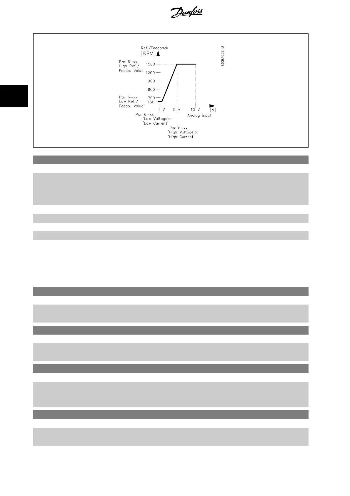
6-10 Terminal 53 Low Voltage
Range: Function:
0.07 V* [0.00 - par. 6-11 V] Enter the low voltage value. This analog input scaling value should correspond to the low reference/
feedback value set in par.6-14
Terminal 53 Low Ref./Feedb. Value
.
6-11 Terminal 53 High Voltage
Range: Function:
10.00 V* [par. 6-10 - 10.00 V] Enter the high voltage value. This analog input scaling value should correspond to the high refer-
ence/feedback value set in par.6-15
Terminal 53 High Ref./Feedb. Value
.
6-12 Terminal 53 Low Current
Range: Function:
4.00 mA* [0.00 - par. 6-13 mA] Enter the low current value. This reference signal should correspond to the low reference/feedback
value, set in par.6-14
Terminal 53 Low Ref./Feedb. Value
. The value must be set at >2 mA in order
to activate the Live Zero Time-out Function in par.6-01
Live Zero Timeout Function
.
6-13 Terminal 53 High Current
Range: Function:
20.00 mA* [par. 6-12 - 20.00 mA] Enter the high current value corresponding to the high reference/feedback set in par.6-15
Terminal
53 High Ref./Feedb. Value
.
3 Parameter Description ADAP-KOOL
®
Drive Programming Guide
86
MG.11.N1.02 - VLT
®
is a registered Danfoss trademark
3