AK-CC 550A Manual RS8FS402 © Danfoss 2016-03 33
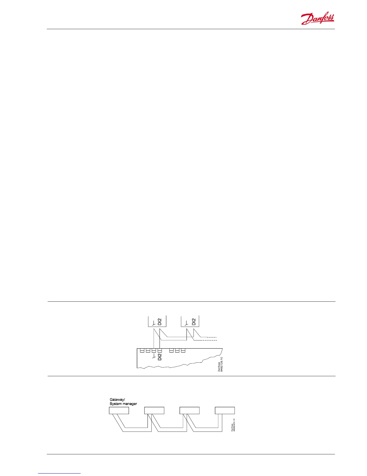
Coordinated defrost via
data communication
Coordinated defrost via
cable connections
The following controllers can be connected
up in this way:
EKC 204A, AK-CC 210, AK-CC 250,
AK-CC 450, AK-CC 550A,
Refrigeration is resumed when all
controllers have “released” the signal for
defrost.
The setting of controllers to coordinate
their defrosting takes place in the
gateway/system manager.
Refrigeration is resumed when all
controllers have “released” the signal for
defrost.
DO1
Connection of expansion valve type AKV or AKVA. The coil must
be a 230 V a.c. coil.
DO2
Alarm
There is a connection between terminal 7 and 8 in alarm
situations and when the controller is without power.
Rail heat and heating element in drip tray
There is connection between terminal 7 and 9 when heating
takes place.
Night blind
There is connection between terminal 7 and 9 when the night
blind is up.
Suction line valve
There is connection between terminal 7 and 9 when the
suction line must be open.
DO3
Refrigeration, Rail heat, Heat function, Defrost 2
There is connection between terminal 10 and 11 when the
function must be active.
Heating element in drip tray
There is connection between terminal 10 and 11 when heating
takes place.
DO4
Defrost
There is connection between terminal 12 and 14 when
defrosting takes place.
Hot gas / drain valve
There is connection between terminal 13 and 14 during normal
operation.
There is connection between terminal 12 and 14 when the hot
gas valves must open.
DO5
Fan
There is connection between terminal 15 and 16 when the fan
is on.
DO6
Light relay
There is connection between terminal 17 and 18 when the
light must be on.
Rail heat, Compressor 2
There is connection between terminal 17 and 19 when the
function must be active.
DI3
Digital input signal.
The signal must have a voltage of 0 / 230 V AC.
The function is dened in o84.
Data communication
If data communication is used, it is important that the installation
of the data communication cable is performed correctly.
See separate literature No. RC8AC…
Electric noise
Cables for sensors, DI inputs and data communication must be
kept separate from other electric cables:
- Use separate cable trays
- Keep a distance between cables of at least 10 cm
- Long cables at the DI input should be avoided
Installation considerations
Accidental damage, poor installation, or site conditions, can give
rise to malfunctions of the control system, and ultimately lead to a
plant breakdown.
Every possible safeguard is incorporated into our products to
prevent this. However, a wrong installation, for example, could still
present problems. Electronic controls are no substitute for normal,
good engineering practice.
Danfoss will not be responsible for any goods, or plant compo-
nents, damaged as a result of the above defects. It is the installer's
responsibility to check the installation thoroughly, and to t the
necessary safety devices.
Special reference is made to the necessity of signals to the
controller when the compressor is stopped and to the need of
liquid receivers before the compressors.
Your local Danfoss agent will be pleased to assist with further
advice, etc.
Max. 10