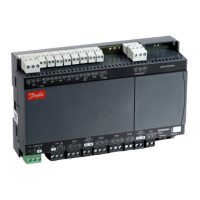
126 Capacity controller RS8HE202 © Danfoss 2017-07 AK-PC 781A
Display of suction pressure and condensing pressure
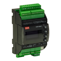
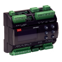
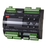
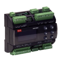
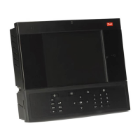
One to four separate displays can be connected to the controller.
Connection is accomplished by means of wires with plug
connections. The display may be placed in a control box front, for
example.
When a display is connected, it will show the value for what is indi-
cated in the setup. It can be:
compressors regulation sensor
P0 i temperature
P0 i bar-absolute
Pctrl bar-absolute
S4
Ss
Sd
Condensors regulation sensor
Tc
Pc bar-absolute
S7
Sgc
Shp
Pgc bar-absolute
Prec bar-absolute
Stw8
Shr8
Speed Compressor
Display Primary readout * Secondary readout
A Regulation sensor suction
pressure
Regulation sensor con-
denser
B Regulation sensor con-
denser
Regulation sensor suction
pressure
C SS None
D SD None
* The primary reading can be changed to other measurements, if required.
When (on plug A) a display with control buttons is chosen, a sim-
ple operation via a menu system can be performed in addition to
the display of suction pressure and condensing pressure:
If you want to see one of the values for what is given under "func-
tion" you should use the buttons in the following way:
1. Press on the upper button until a parameter is shown
2.Press on the upper or lower button and find the parameter you
want to read
3. Press on the middle button until the value of the parameter is
displayed.
After a short time, the display will return automatically to the
"Read out display".
No. Function Cond. Suc-
tion
Pack
o57 Capacity settings for condenser
0: MAN, 1: OFF, 2: AUTO
x x
o59 Capacity setting for suction group
0: MAN, 1: OFF, 2: AUTO
x x
h15 High pressure. Setting of Pgc minimum x
h16 High pressure. Setting of HP-control mode: Automatic /
manual
x
h17 High pressure. Manuel mode. Setting of valves opening
degree
x
h18 Heat recovery. Reference for Shr8-temperature x
h19 Heat recovery. Setting of heat recovery control mode:
Automatic / off
x
o30 Refrigerant setting x x x
058 Manual setting of condenser capacity x x
o60 Manual setting of suction capacity x x
o62 Select of predefined configuration
This setting will give a selection of predefined combina-
tions which at the same time establish the connections
points.. At the end of the manual an overview of options
and connection points is shown. After the configuration
of this function the controller will shut down and restart
x x x
o93 Lock of configuration
It is only possible to select a predefined configuration or
change refrigerant when the configuration lock is open.
0 = Configuration open
1 = Configuration locked
x x x
r12 Main switch
0: Controller stopped
1: Regulating
x x x
r23 Set point suction pressure
Setting of required suction pressure reference in °C
x x
r24 Suction pressure reference
Actual reference temperature for compressor capacity
x x
r28 Set point condenser
Setting of required condenser pressure in °C
x x
r29 Condenser reference
Actual reference for temperature for condenser capacity
x x
r57 Po evaporating pressure in °C x x
r86 Receiver control. Reference for Prec x
r87 Receiver control. Setting of the receiver control mode :
Automatic / manual
x
r88 Receiver control. Manual mode. Setting of the valves
opening degree
x
t49 Hot water. Reference for Stw8-temperature x
t50 Hot water. Setting of hot water control mode: Automatic
/ off
x
u16 Actual media temperature measured with S4 x x
u21 Superheat in suction line x x
u44 Sc3 out door temperature in °C x x
u48 Actual regulation status on condenser
0: Power up
1: Stopped
2: Manuel
3: Alarm
4: Restart
5: Standby
6: Unloaded
7-9: Part loaded
10: Full loaded
11: Running
x x
u49 Cut in condenser capacity in % x x
u50 Reference for condenser capacity in % x x
u51 Actual regulation status on suction group MT-circuits
0: Standby
1: Normal control
2: Compressor alarm
3: ON timer aktiv
4: OFF timer activ
5: Normal control
6: Injection ON delay
7: Coordination
8: Compressor 1 delay is activ
9: Pump down
10: Sensor error
11: Load shed is activ
12: High Sd
13: High Pc
14: Manuel control
15: OFF
16: Inrush guard
17: Min. cap. req
18: Pump delay
x x
u52 Cut in compressor capacity in % x x
u53 Reference for compressor capacity x x
u54 Sd discharge gas temperature in °C x x
u55 Ss Suction gas temperature in °C x x
u98 Actual temperature for S7 media sensor x x
u99 Pctrl pressure in °C (cascade pressure) x x
U01 Actual Pc condensing pressure in °C x x
AL1 Alarm suction pressure x x
AL2 Alarm condenser x x
- - 1 Initiation, Display is connected to output "A", (- - 2 =
output "B" etc.)
x x x

 Loading...
