38 Capacity controller RS8HE202 © Danfoss 2017-07 AK-PC 781A
11
Signal Module Point Terminal Active at
Compressor 1 Gen. Safety
4
1 (DI 1) 1 - 2 Open
Compressor 2 Gen. Safety 2 (DI 2) 3 - 4 Open
Compressor 3 Gen. Safety 3 (DI 3) 5 - 6 Open
Compressor 4 Gen. Safety 4 (DI 4) 7 - 8 Open
Start/stop heat recovery hr 5 (DI 5) 9 - 10 Closed
All compressors common safety 6 (DI 6) 11 - 12 Open
Flow switch FStw 7 (DI 7) 13 - 14 Open
Flow switch FShr 8 (DI 8) 15 - 16 Open
Signal Module Point Terminal Signal type
Temp. gas cooler outlet Sgc
5
1 (AI 1) 1 - 2 Pt 1000
Temp. by-pased gas Shp 2 (AI 2) 3 - 4 Pt 1000
Start/stop heat recovery tw
3 (AI 3) 5 - 6
Closed
Gas cooler pressure Pgc
4 (AI 4) 7 - 8
AKS 2050-159
Speed control, compressor 5 (AO 1) 9 - 10
0 - 10 V
Speed control, gas cooler fan 6 (AO 2) 11 - 12 0 - 10 V
Speed control, pump - tw 7 (AO 3) 13 - 14 0 - 10 V
Speed control, pump - hr 8 (AO 4) 15 - 16 0 - 10 V
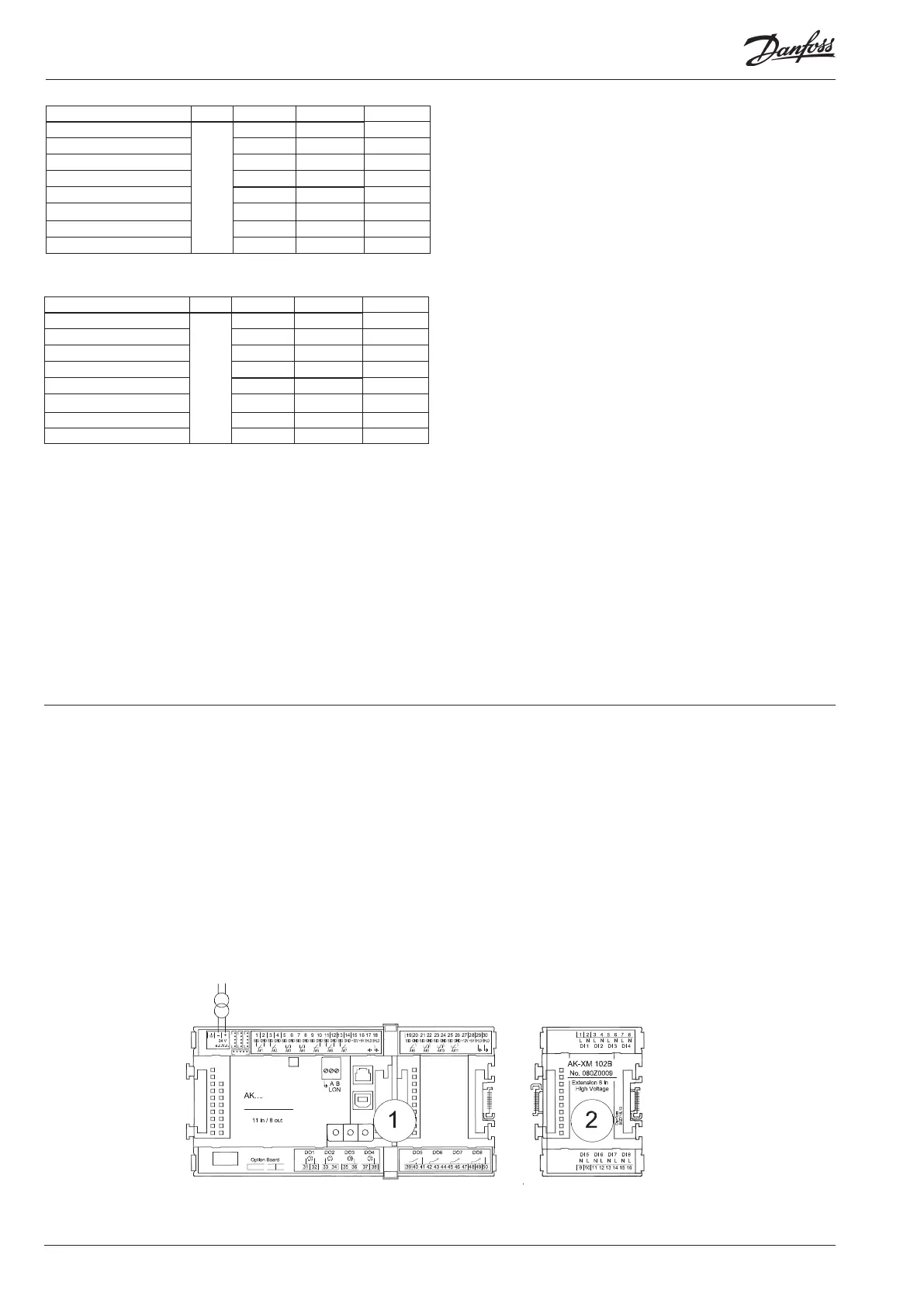
Connection diagram
Drawings of the individual modules may be
ordered from Danfoss.
Format = dwg and dxf.
You may then yourself write the module
number in the circle and draw the individual
connections.
The supply voltage for the pressure
transmitter should be taken from
the same module that receives the
pressure signal.