AK-PC 781A Capacity controller RS8HE202 © Danfoss 2017-07 51
Refrigerating plant example
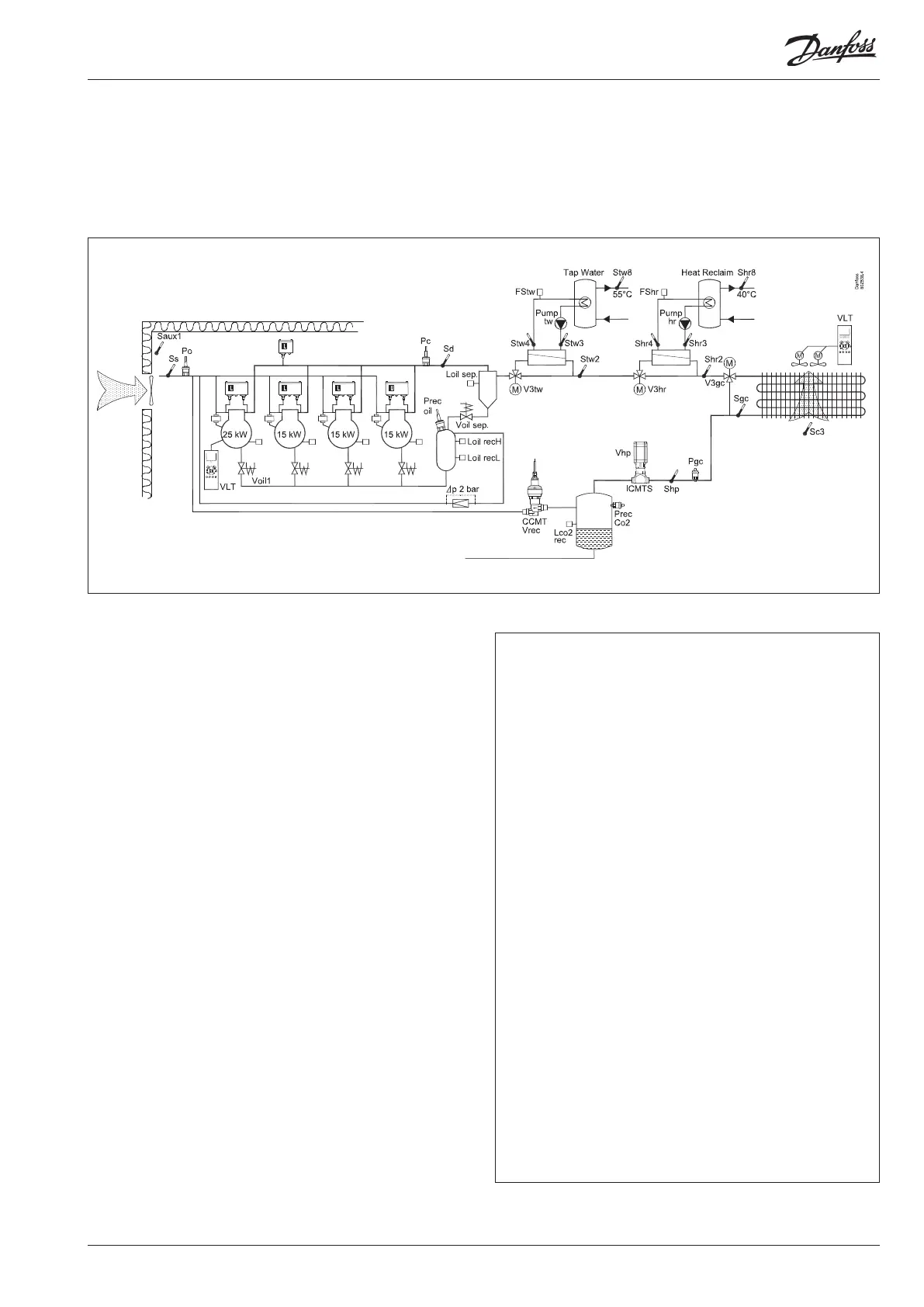
We have decided to describe the setup by means of an example
comprising a MT compressor group and a high pressure control.
The example is the same as the one given in the "Design" section,
i.e. the controller is an AK-PC 781A + extension modules.
There is also an internal main switch as a setting. Both, this and the
external compressor stop must be “ON” before any adjustment is made.
Warning
The main switch will stop all regulations, including high-pressure regula-
tion.
Compressor Group
• MT circuit
• Refrigerant CO2 (R744)
• Variable compressor and 3 single step compressors
• 4 only compressors with "Best fit"
• Safety monitoring of each compressor
• Common high-pressure monitoring
• Po setting -15°C, night displacement 5 K
• Oil management of each compressor
High pressure control:
• Gas cooler with speed controlled fans (Pgc Max. = 100 bar)
• High pressure control with signal from Sgc and Shp
• Pc regulates floating based on outdoor temperature sensor Sc3
• Control of high pressure valve ICMTS
• Heat recovery for hot tap water. Relay and 0-10 V
• Heat recovery for heating. Relay and 0-10 V
Receivers:
• Monitoring of liquid level of refrigerant
• Control of pressure in refrigerant receiver (reference 34 bar)
• Control of pressure in oil receiver
Fan in plant room
• Thermostat control of fan in engine room
Safety functions:
• Monitoring of Po, Pc, Sd and superheat in suction line
• Po max = -5°C, Po min = -35°C
• Pc max = 103.5 bar
• Sd max = 120°C
• SH min = 5 °C, SH max = 35 °C
• Monitoring of low and high level in oil receiver
Other
• Start/stop of heat recovery tw and hr
• External compressor stop used