AK-PC 781A Capacity controller RS8HE202 © Danfoss 2017-07 67
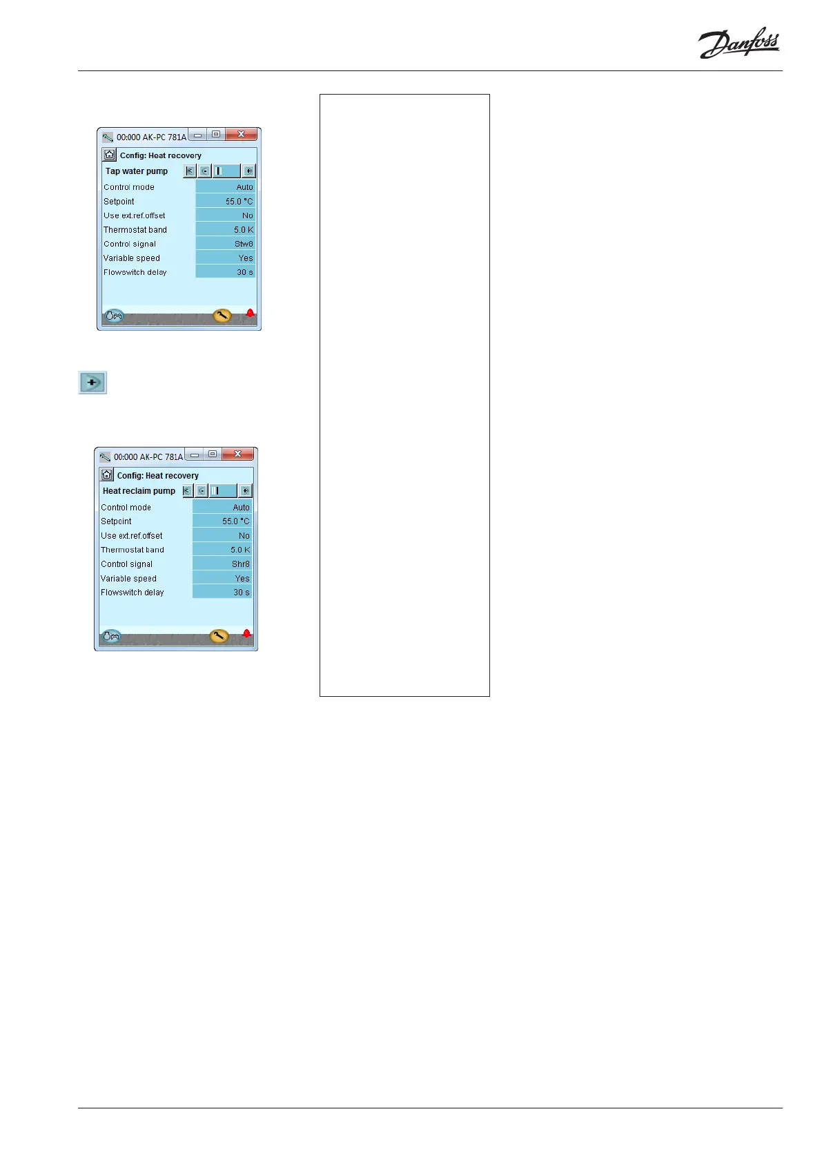
5. Setup values for tap water cir-
cuits
Press the +-button to go on to the
next page
6. Setup values for heating circuit
5 - Tap water circuits (settings are available only when the
refrigerant selected is CO2, and shall be regulated on a
circuit for tap water).
Control mode: Here the regulation of the circuit can be
started (auto) and stopped (off).
Setpoint: The required temperature for the sensor Stw8
can be set here.
Use ext. ref. offset
A 0-10 V signal must displace the temperaturreference.
Max. Ext. ref. offset
Reference displacement at max. signal (10 V)
Thermostat band: The acceptable temperature variation
around the reference:
Control signal. . Choose between:
Stw8: if regulation shall be done using only this sensor.
S4-S3: (and a Delta T value) if the controller shall regulate
using this temperature difference, until the Stw8 refer-
ence is met. (During S4-S3 regulation, the pump must
always be speed-regulated).
Stw8 + Stw8A: if two temperature sensors are installed in
the hot water receiver.
Stw4: regulation is done using this sensor
Variable speed: Here the pump type is selected. Either
variable speed or on/off.
Advanced settings: The following options are made avail-
able:
Flow switch: Must normally be selected for safety purposes
Kp: Amplification factor
Tn: Integration time
Min. pump speed: Pump speed for start/stop
Max. pump speed: The pump's max. permissible speed
Flowswitch delay: Duration of stable signal before the new
status is used in the regulation.
6 - Heat reclaim circuits (settings are available only when
the refrigerant chosen is CO2, and regulation shall be
done using a circuit for heating).
Control mode: Here the regulation of the circuit can be
started (auto) and stopped (off).
Setpoint: Here the required temperature of sensor Shr8 (or
Shr4) is set.
Use ext. ref. offset
A 0-10 V signal must displace the temperaturreference.
Max. Ext. ref. offset
Reference displacement at max. signal (10 V)
Thermostat band: The permissible temperature variation
around the reference:
Control signal: Choose between:
Shr8: if regulation shall be done using only this sensor.
S4-S3: (and a Delta T value) if the controller shall regulate
using this temperature difference, until the Shr8 refer-
ence has been met.
Shr4: regulation is done using this sensor. (During S4-S3
regulation or Shr4 regulation the pump shall always be
speed-regulated).
Variable speed: Here the pump type is selected. Either
variable speed or on/off.
Heat consumers: (Only when the condensation pressure
shall be increased during heat recovery). The number of
signals that can be received is set here. The signal can be
either 0-10 V or 0-5 V. (Settings under "Advanced" will be
used 0-100% for the signal).
Heat consumer filter
The highest of the received signals are made known over
this period
Additional heat output
The function will reserve a relay. The relay will pull in when
the signal for the heat removers reaches 95%.
Flowswitch delay: Duration of stable signal before the new
status is used in the regulation.
In our example we use the
settings shown
In our example we use the
settings shown
Configuration - continued