180R9346 | AQ240486503020en-001702 | 45© Danfoss | 2023.03
Operation guide Installation, Operation and Maintenance APP 53-92 pumps
The design of the system must ensure that
self-emptying of the pump during standstill is
avoided.
The inlet pressure of the pump must never
exceed the outlet pressure. This may typically
occur in boosted or open-ended systems with
direct water supply.
2.1 Open-ended systems with direct water
supply
Axial piston pumps require a certain inlet
pressure to perform as intended. Please nd min.
required feed pressure in the pump data sheet.
Please also note that feed pressure must not
exceed 5 barg (72.5 psig).
2. System design
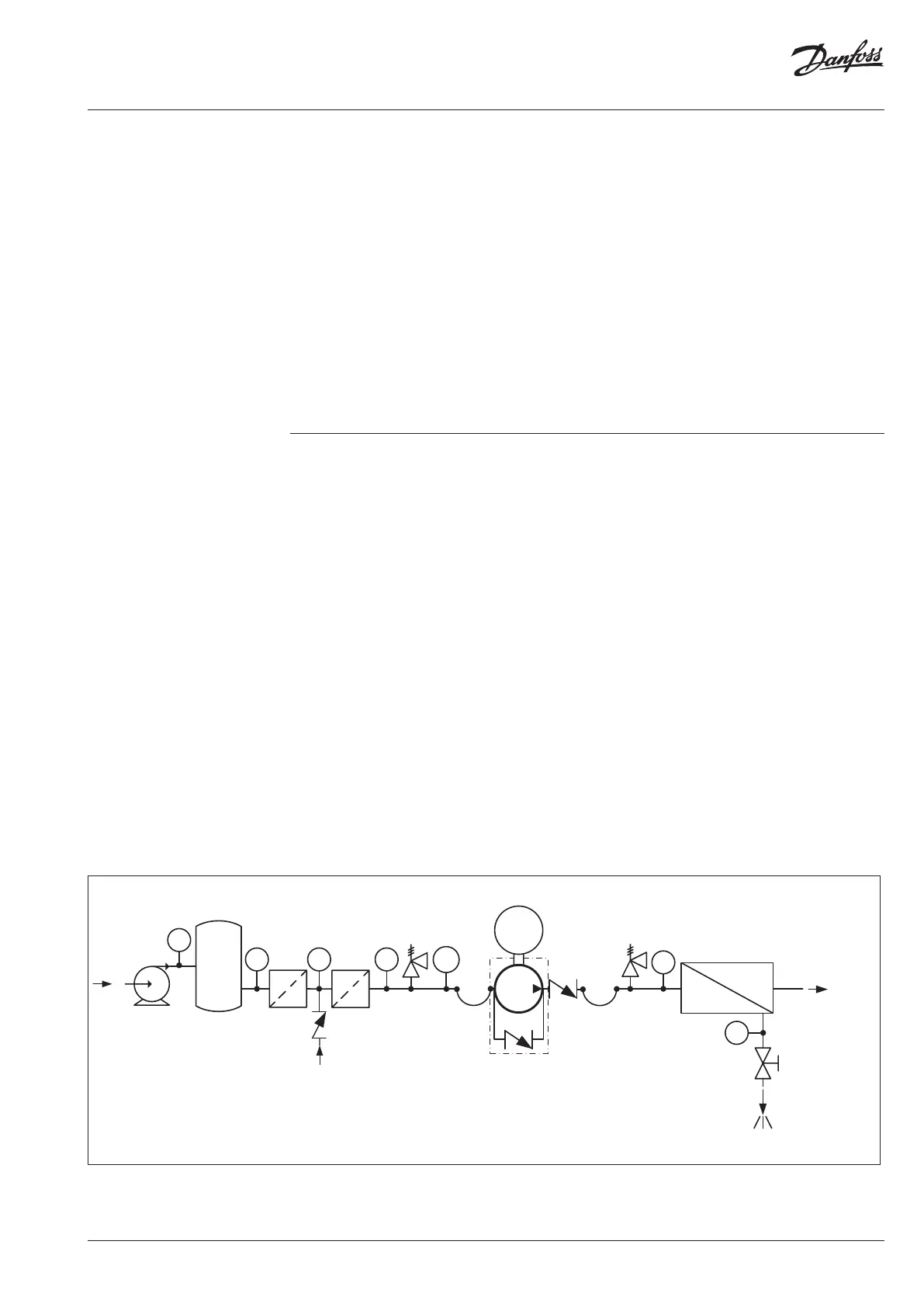
2.2
Preferred RO system design without ERD
1. Dimension the inlet line to obtain minimum
pressure loss (large ow, minimum pipe
length, minimum number of bends/
connections, and ttings with small
pressure losses).
2. Place an inlet lter (1) in front of the APP
pump (2). Please consult Danfoss lter data
sheet for guidance on how to select the
right lter. Thoroughly clean pipes and
ush system prior to start-up.
3. Place a monitoring pressure switch (3) set at
min. inlet pressure between lter and
pump inlet. The monitoring switch must
stop the pump at pressures lower than
minimum pressure.
4. Use exible hoses (4) to minimize vibrations
and noise.
5. In order to eliminate the risk of damage and
cavitation, a positive pressure at the inlet (5)
is always to be maintained at min. inlet
pressure and max. inlet pressure.
It is recommend to install safety valve or a
pressure relief valve (9) in order to avoid high-
pressure peaks in case the pump stops momen-
tarilly or is spinning backwards.
6. For easy system bleeding and ushing, a
bypass non-return valve (6) is integrated in
the APP pump.
7. A non-return valve (7) in outlet can be
installed in order to avoid backspin of the
pump. The volume of water in the mem-
brane vessel works as an accumulator and
will send ow backwards in case of the
pump stops momentarily.
8. A safety valve or a pressure relief valve (8)
can be installed in order to avoid system
damage as the Danfoss APP pump creates
pressure and ow immediately after start-
up, regardless of any counter pressure.
Note: If a non-return valve is mounted in the
inlet line, a low-pressure relief valve is also
required between non-return valve and pump
as protection against high-pressure peaks.
Media filter
M
Brine
Permeate
Feed
PI
PI PI
PT
PI
PI
PI
Fresh water
permeat flush
To protect the pump from being damaged by
peaks of high-pressure in case the pump stops
momentarily, it is required to mount a low-
pressure relief valve on the inlet line.
Note: The inlet connection must be properly
tightened, as possible entrance of air will cause
cavitation.