180R9346 | AQ240486503020en-001702 | 49© Danfoss | 2023.03
Operation guide Installation, Operation and Maintenance APP 53-92 pumps
3.4 Direction of rotation
Is indicated by an arrow engraved in the ange
of the pump.
3.5 Orientation
APP 53-92 can be mounted/orientated in steps of
45 degrees. Please see Data sheet 521B1340.
4. Building up the
pump unit with jaw
coupling
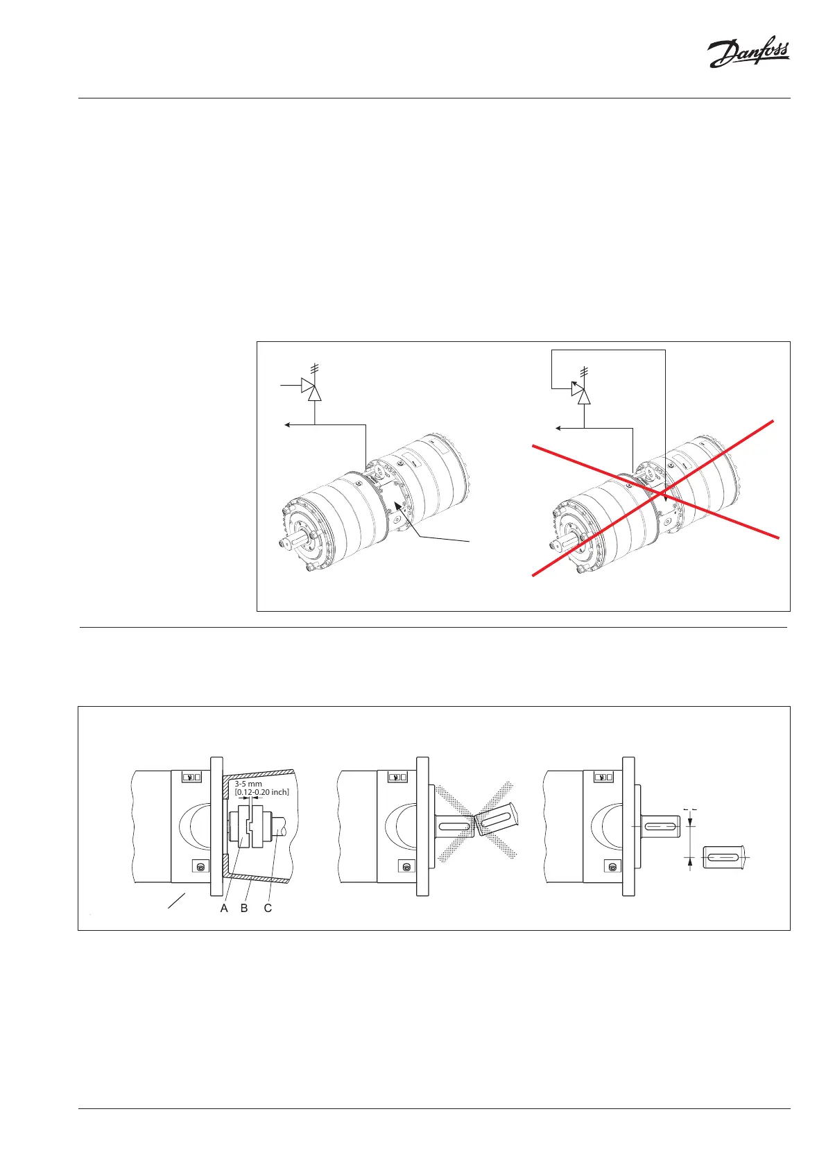
D
A: Elastic coupling
B: Bell housing
C: Motor shaft
D: Pump ange
4.1 Mounting
1. Mount the coupling ush with the pump
shaft end or maximum 1 mm oset from
the pump shaft end. Ensure an air gap
between coupling parts of 3-5 mm (0.12-0.2
inch).
2. Mount the bell housing on pump. Secure
nuts with the right torque.
3. Measure the longest distance “A” from top
of bell housing to the button of coupling
claw.
4. Mount the coupling on motor shaft. Ensure
the coupling and motor ange are not in
contact with each other.
5. Measure from motor ange to the top of
the coupling. That measurement “B” shall
be 3-5 mm (0.12-0.2 inch) shorter than the
measurement “A”.
(“A” and “B” can be found on the next
page).
The opening characteristics of the valve must not
result in peak pressures higher than 100 barg
(1450 psig).
The valve should be placed as close to the pump
as possible.
We recommend to install exible soft hoses both
in the inlet and outlet lines.
3.6 Protection from too high pressures
The pump should be protected against too high
pressure by means of a safety valve or a pressure
relief valve.
The valve outlet must not be connected directly to the pump suction line.
It must be connected directly to the drain.
Outlet
Outlet Inlet
IMPORTANT
When using jaw coupling it is critiacal
that the recommended measure-
ments are kept.
max. 0.25 mm
max. 0.01 inch
Inlet