Installation Guide CF-MC Master Controller
6
01/2016 VIUHK902 Danfoss Heating Solutions
4.9 More (2 to 3) CF-MC Master Controllers
Note! To have a troublefree installation of the CF-MC Master Controller 2 and/or 3, it is recommended to
complete installation of the CF-MC Master Controller 1.
CF-MC Master Controller 1 should be the one connected to the local supply pump.
• Up to 3 CF-MC Master Controllers can be connected in one system.
• If there are 2 or 3 CF-MC Master Controllers, connect them to a 230 V power supply within a
distance (max. 1.5 m) from CF-MC Master Controller 1, allowing simultaneous handling of all the
CF-MC Master Controllers.
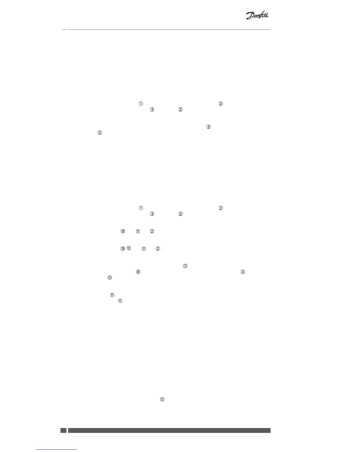
Activate Install mode on CF-MC Master Controller 1 (fig. 20):
• Use the menu selection button to select the Install mode. Install LED flashes.
• Activate Install mode by pressing OK . Install LED goes ON.
Initiate installation on CF-MC Master Controller 2 or 3 (fig. 20):
• Activate installation to CF-MC Master Controller 1 by pressing OK .
• Install LED flickers during communication and goes OFF when installation is complete.
• Relocate CF-MC Master Controller 2 and/or 3 if necessary. Link test will be initiated automati-
cally on reconnection to 230 V power supply.
• If CF-MC Master Controller 2 and/or 3 has it’s own pump, the relays for pump and boiler must
be configured accordingly (see chapter 6.5).
Note! Later removal of CF-MC Master Controller 2 or 3 from CF-MC Master Controller 1 can only be done
by resetting CF-MC Master Controller 1 (see chapter 7.2).
4.10 CF-RS, -RP, -RD and -RF Room Thermostats
Note!
Assignment of Room Thermostats to CF-MC Master Controller should be within a distance of 1.5 m.
Activate Install mode on CF-MC Master Controller (fig. 20):
• Use the menu selection button to select the Install mode. Install LED flashes.
• Activate Install mode by pressing OK . Install LED goes ON.
Activate Install mode on CF-RD and -RF Room Thermostats (fig. 20/21):
• Press the push button . LED and flicker during communication.
Activate Install mode on CF-RS and -RP Room Thermostats (fig. 20/21):
• Press the push button / . LED and flicker during communication.
Select output on CF-MC Master Controller (fig. 20/22):
• All available output LEDs on CF-MC Master Controller light up, and the first one flashes.
• Press output selection button to select desired output (flashes). Accept with OK .
• All output LEDs go OFF. Selected output stays ON shortly.
Room Thermostat installation status (fig. 21):
• Satisfactory: LED goes OFF.
• Not satisfactory: LED flashes 5 times.
Note!
A Room Thermostat can be assigned to several outputs if needed by repeating the installation process.
4.11 Other System Components
The installation procedure of other system components to the CF-MC Master Controller (CF-RC Re-
mote Controller, and CF-RU Repeater Unit) is described in the enclosed instructions for these system
components.
4.12 Transmission Test (Link Test)
The transmission test (link test) between the CF-MC Master Controller and other system components,
is initiated from the other system components like CF-RU Repeater Unit, CF-RC Remote Controller,
etc. See the enclosed instruction for these components for transmission test (link test) procedures.
Room Thermostats
When the transmission test (link test) from a Room Thermostat is received by the CF-MC Master
Controller, the assigned output(s) will flash. This makes it possible to identify the outputs to which a
Room Thermostat has been assigned (fig. 22 - ).