Slope 2175
Setting range Factory setting
0.1 ... 4.0 1.8
Adjust the ‘Slope’ of the heat curve, if required.
The heat curve slope depends on the heating system and area specific design
parameters.
Example I
Design parameter:
Designed outdoor temperature (T
out
) -12 °C
Designed flow temperature (T
flow
) 80 °C
Designed room temperature (T
room
) 20 °C
For designed flow temperature higher than 40 °C, the heat curve slope (S) can be
calculated as:
S =
T
flow
- 25
2.5 x T
room
- T
out
- 30
S =
80 - 25
2.5 x 20 - (- 12) - 30
S ≈ 1.7
Example II
Design parameter:
Designed outdoor temperature (T
out
) -20 °C
Designed flow temperature (T
flow
) 35 °C
Designed room temperature (T
room
) 21 °C
For designed flow temperatures lower than 40 °C, the heat curve slope (S) can be
calculated as:
S =
T
flow
- 20
1.3 (2.5 x T
room
- T
out
- 30)
S =
35 - 20
1.3 (2.5 x 21 - (- 20) - 30)
S ≈ 0.3
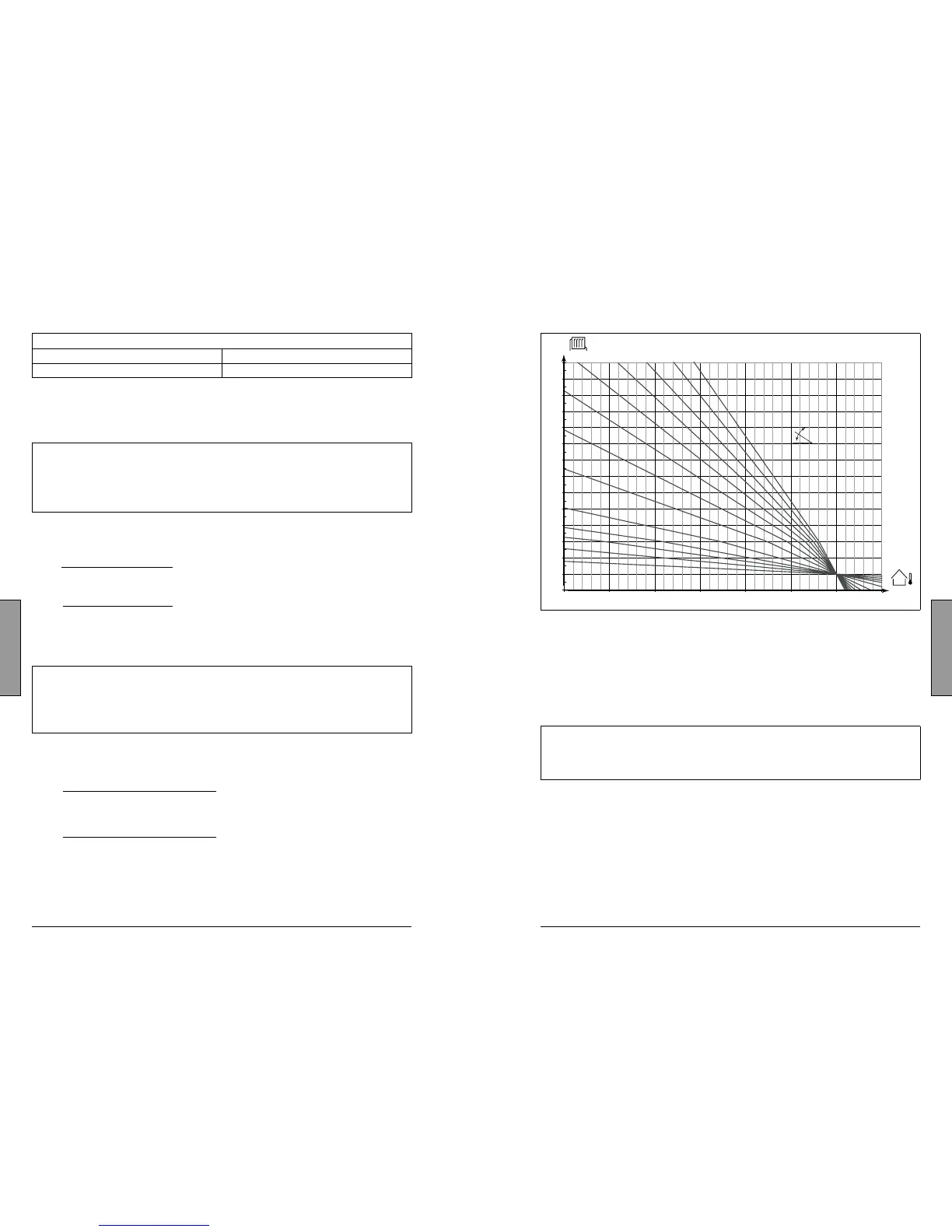
For quick setting, the graph can be used. The graph is intended for a T
room
of 20 °C. If the
design data from example I is used, the slope will be approx. 1.7.
How to determine another heat curve, if necessary:
Choose the calculated flow temperature for your system and the determined min.
outdoor temperature for your area. Pick the heat curve closest to the crossing point of
these two values.
The setting of the desired room temperature has an influence on the calculated flow
temperature (heat curve), no matter if a room temperature sensor is connected or not.
Floor heating systems
This controller is factory set for radiator systems, which typically are high flow temperature
systems. To control floor heating systems, which typically are low flow temperature systems,
you need to change the ‘Slope’ according to your type of system (typical setting: 1.0).
 Loading...