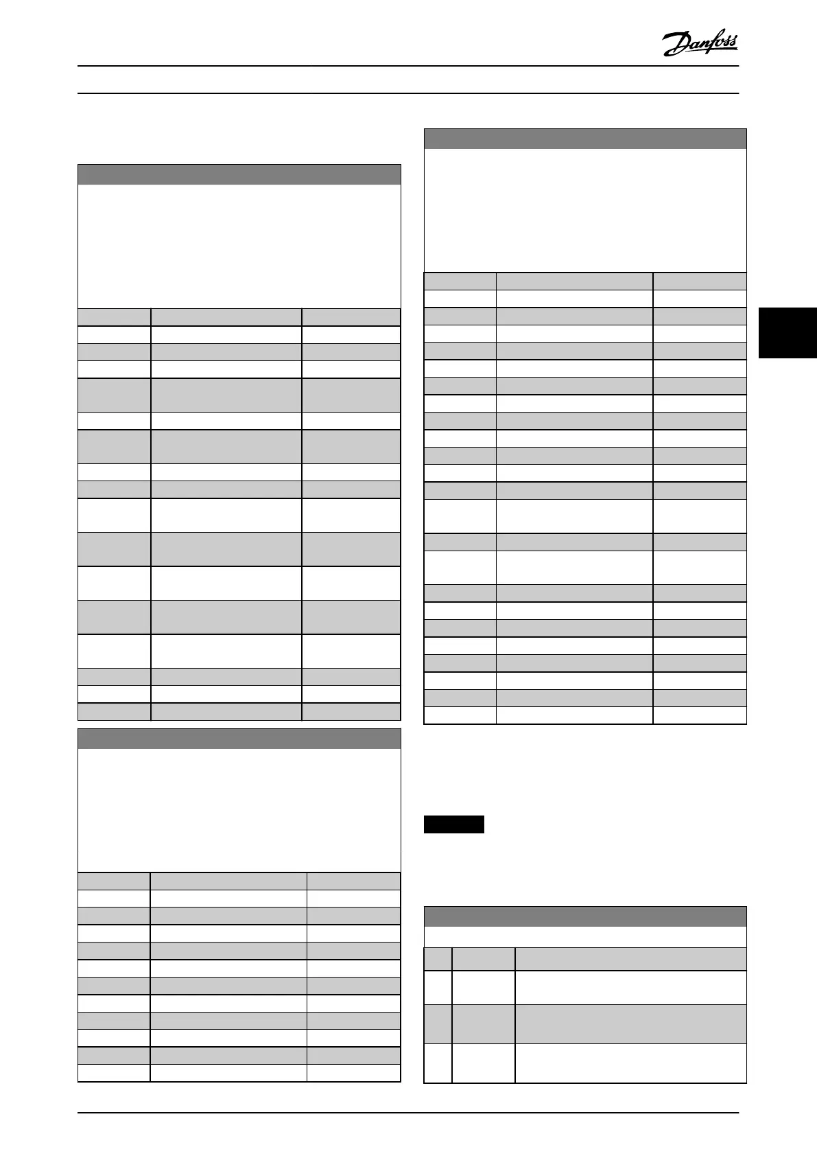
5.1.4 8-4* FC MC Protocol Set
8-42 PCD Write Conguration
Enter up to 16 dierent preset mapping 0–15 in this parameter,
using array programming. If this parameter is active, addresses
2810–2825 represent values of the 16 parameters. If this
parameter is not active, addresses 2810 and 2811 are used as
input-data-drive control word and bus reference. Addresses
2812–2825 are reserved.
Option: Function:
[0] None
[1] [302] Minimum Reference
[2] [303] Maximum Reference
[3] [341] Ramp 1 Ramp up time
[4] [342] Ramp 1 Ramp down
time
[5] [351] Ramp 2 Ramp up time
[6] [352] Ramp 2 Ramp down
time
[7] [380] Jog Ramp Time
[8] [381] Quick Stop Time
[9] [412] Motor Speed Low Limit
[Hz]
[10] [414] Motor Speed High Limit
[Hz]
[11] [590] Digital & Relay Bus
Control
[12] [676] Terminal45 Output Bus
Control
[13] [696] Terminal 42 Output Bus
Control
[14] [894] Bus Feedback 1
[15] FC Port CTW
[16] FC Port REF
8-43 PCD Read Conguration
Enter up to 16 dierent preset mapping (0-15) in this parameter,
using array programming. If this parameter is active, addresses
from 2910 to 2925 represent values of the 16 parameters. If this
parameter is not active, addresses 2910 and 2911 are used as
status word register and main actual value. Addresses from 2912
to 2925 are reserved.
Option: Function:
[0] None
[1] [1500] Operation Hours
[2] [1501] Running Hours
[3] [1502] kWh Counter
[4] [1600] Control Word
[5] [1601] Reference [Unit]
[6] [1602] Reference %
[7] [1603] Status Word
[8] [1605] Main Actual Value [%]
[9] [1609] Custom Readout
[10] [1610] Power [kW]
[11] [1611] Power [hp]
8-43 PCD Read Conguration
Enter up to 16 dierent preset mapping (0-15) in this parameter,
using array programming. If this parameter is active, addresses
from 2910 to 2925 represent values of the 16 parameters. If this
parameter is not active, addresses 2910 and 2911 are used as
status word register and main actual value. Addresses from 2912
to 2925 are reserved.
Option: Function:
[12] [1612] Motor Voltage
[13] [1613] Frequency
[14] [1614] Motor Current
[15] [1615] Frequency [%]
[16] [1616] Torque [Nm]
[17] [1618] Motor Thermal
[18] [1630] DC Link Voltage
[19] [1634] Heatsink Temp.
[20] [1635] Inverter Thermal
[21] [1638] SL Controller State
[22] [1650] External Reference
[23] [1652] Feedback [Unit]
[24] [1660] Digital Input 18,19,27,33
[25] [1661] Terminal 53 Switch
Setting
[26] [1662] Analog Input 53(V)
[27] [1663] Terminal 54 Switch
Setting
[28] [1664] Analog Input 54
[29] [1665] Analog Output 42 [mA]
[30] [1671] Relay Output [bin]
[31] [1672] Counter A
[32] [1673] Counter B
[33] [1690] Alarm Word
[34] [1692] Warning Word
[35] [1694] Ext. Status Word
5.1.5 8-5* Digital/Bus
Parameters for conguring the control word merging.
NOTICE
These parameters are active only when
parameter 8-01 Control Site is set to [0] Digital and control
word.
8-50 Coasting Select
Option: Function:
Select the trigger for the coasting function.
[0] Digital
input
A digital input triggers the coasting function.
[1] Bus A serial communication port or the eldbus
triggers the coasting function.
[2] Logic AND The eldbus/serial communication port and a
digital input trigger the coasting function.
Parameters Programming Guide
MG07H102 Danfoss A/S © 06/2016 All rights reserved. 23
5 5

 Loading...


