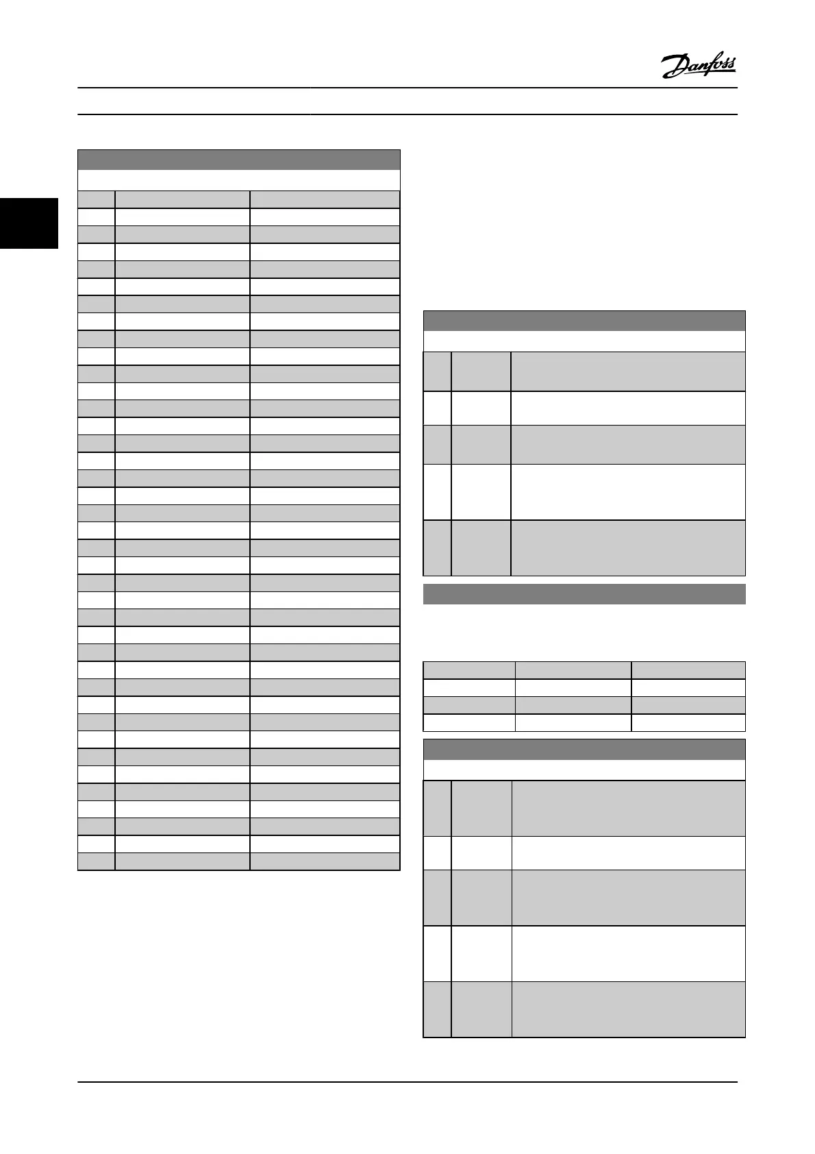
8-43 PCD read configuration
Option: Function:
[1677] Analog Out X30/8 [mA]
[1678] Analog Out X45/1 [mA]
[1679] Analog Out X45/3 [mA]
[1684] Comm. Option Status
[1690] Alarm Word
[1691] Alarm word 2
[1692] Warning Word
[1693] Warning word 2
[1694] Ext. Status Word
[1860] Digital Input 2
[3421] PCD 1 Read from MCO
[3422] PCD 2 Read from MCO
[3423] PCD 3 Read from MCO
[3424] PCD 4 Read from MCO
[3425] PCD 5 Read from MCO
[3426] PCD 6 Read from MCO
[3427] PCD 7 Read from MCO
[3428] PCD 8 Read from MCO
[3429] PCD 9 Read from MCO
[3430] PCD 10 Read from MCO
[3440] Digital Inputs
[3441] Digital Outputs
[3450] Actual Position
[3451] Commanded Position
[3452] Actual Master Position
[3453] Slave Index Position
[3454] Master Index Position
[3455] Curve Position
[3456] Track Error
[3457] Synchronizing Error
[3458] Actual Velocity
[3459] Actual Master Velocity
[3460] Synchronizing Status
[3461] Axis Status
[3462] Program Status
[3464] MCO 302 Status
[3465] MCO 302 Control
[3470] MCO Alarm Word 1
[3471] MCO Alarm Word 2
3.10.5 8-5* Digital/Bus
Parameters for configuring the control word Digital/Bus
merging.
NOTE!
These parameters are active only when 8-01 Control Site is set
to [0] Digital and control word.
8-50 Coasting Select
Option: Function:
Select control of the coasting function via the
terminals (digital input) and/or via the bus.
[0] Digital
input
Activates Start command via a digital input.
[1] Bus Activates Start command via the serial communi-
cation port or serial communication option.
[2] Logic AND Activates Start command via the serial communi-
cation bus/serial communication port, AND
additionally via one of the digital inputs.
[3]
*
Logic OR Activates Start command via the serial communi-
cation bus/serial communication port OR via one
of the digital inputs.
8-51 Quick Stop Select
Select control of the quick stop function via the terminals (digital
input) and/or via the bus.
Option: Function:
[0] Digital Input
[1] Bus
[2] Logic AND
[3]
*
Logic OR
8-52 DC Brake Select
Option: Function:
Select control of the DC brake via the terminals
(digital input) and/or via the serial communi-
cation bus.
[0] Digital
input
Activates Start command via a digital input.
[1] Bus Activates Start command via the serial
communication port or serial communication
option.
[2] Logic AND Activates Start command via the serial
communication bus/serial communication port,
AND additionally via one of the digital inputs.
[3]
*
Logic OR Activates Start command via the serial
communication bus/serial communication port
OR via one of the digital inputs.
Parameter Descriptions FC 300 Programming Guide
3-88 MG.33.MA.22 - VLT
®
is a registered Danfoss trademark
3

 Loading...


