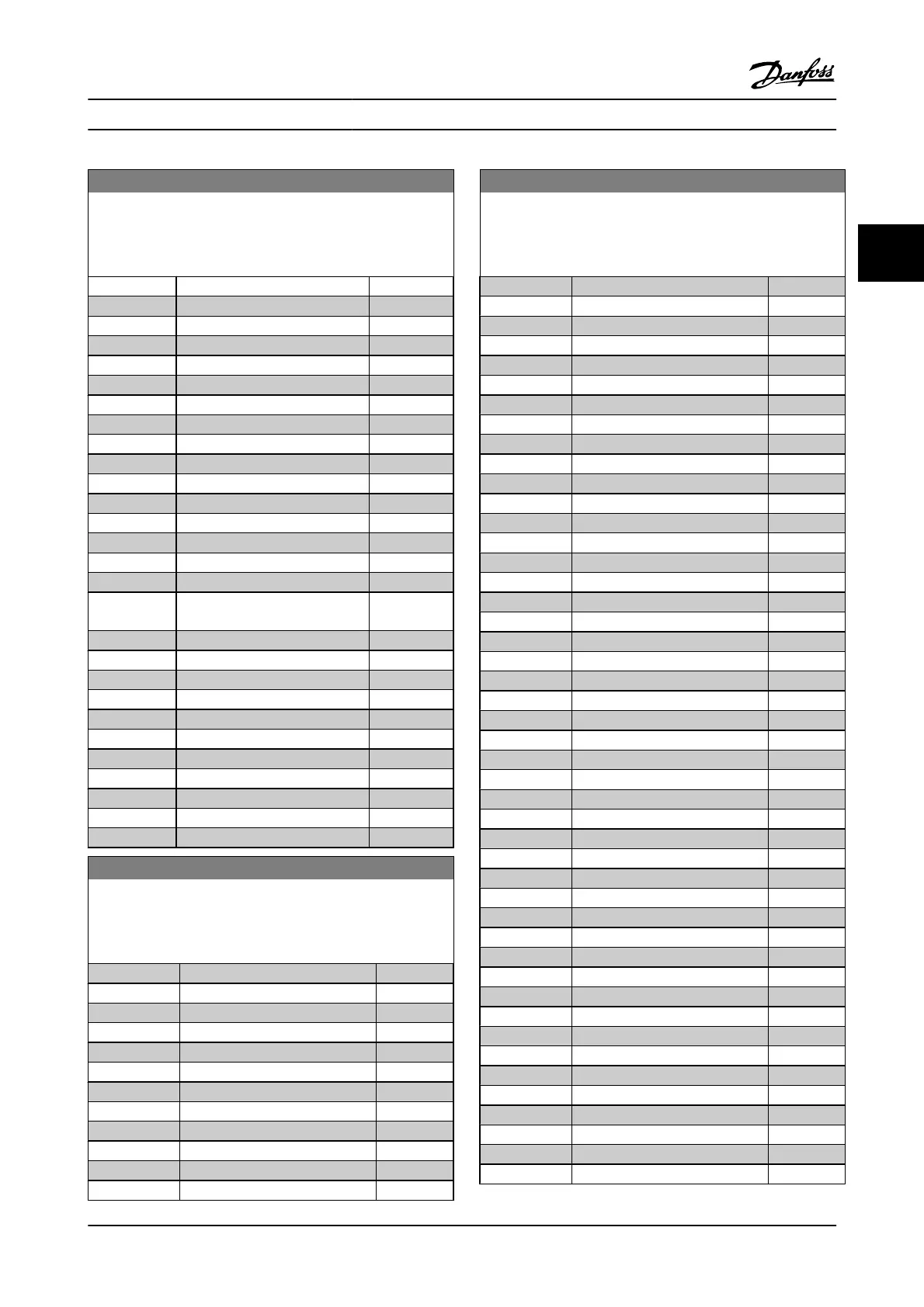
10-11 Process Data Config Write
Select the process write data for I/O assembly instances 101/151.
Elements [2] and [3] of this array can be selected. Elements [0] and
[1] of the array are fixed.
Option: Function:
[417] Torque Limit Generator Mode
[590] Digital & Relay Bus Control
[593] Pulse Out #27 Bus Control
[595] Pulse Out #29 Bus Control
[597] Pulse Out #X30/6 Bus Control
[653] Terminal 42 Output Bus Control
[663] Terminal X30/8 Bus Control
[673] Terminal X45/1 Bus Control
[683] Terminal X45/3 Bus Control
[748] PCD Feed Forward
[890] Bus Jog 1 Speed
[891] Bus Jog 2 Speed
[1680] Fieldbus CTW 1
[1682] Fieldbus REF 1
[1685] FC Port CTW 1
[1686] FC Port REF 1
[3310] Synchronization Factor Master
(M:S)
[3311] Synchronization Factor Slave (M:S)
[3401] PCD 1 Write to MCO
[3402] PCD 2 Write to MCO
[3403] PCD 3 Write to MCO
[3404] PCD 4 Write to MCO
[3405] PCD 5 Write to MCO
[3406] PCD 6 Write to MCO
[3407] PCD 7 Write to MCO
[3408] PCD 8 Write to MCO
[3409] PCD 9 Write to MCO
[3410] PCD 10 Write to MCO
10-12 Process Data Config Read
Select the process read data for I/O assembly instances 101/151.
Elements [2] and [3] of this array can be selected. Elements [0] and
[1] of the array are fixed.
Option: Function:
[0]
*
None
[1472] VLT Alarm Word
[1473] VLT Warning Word
[1474] VLT Ext. Status Word
[1500] Operating Hours
[1501] Running Hours
[1502] kWh Counter
[1600] Control Word
[1601] Reference [Unit]
[1602] Reference %
[1603] Status Word
[1605] Main Actual Value [%]
10-12 Process Data Config Read
Select the process read data for I/O assembly instances 101/151.
Elements [2] and [3] of this array can be selected. Elements [0] and
[1] of the array are fixed.
Option: Function:
[1609] Custom Readout
[1610] Power [kW]
[1611] Power [hp]
[1612] Motor voltage
[1613] Frequency
[1614] Motor Current
[1615] Frequency [%]
[1616] Torque [Nm]
[1617] Speed [RPM]
[1618] Motor Thermal
[1619] KTY sensor temperature
[1620] Motor Angle
[1621] Torque [%] High Res.
[1622] Torque [%]
[1625] Torque [Nm] High
[1630] DC Link Voltage
[1632] Brake Energy /s
[1633] Brake Energy /2 min
[1634] Heatsink Temp.
[1635] Inverter Thermal
[1638] SL Controller State
[1639] Control Card Temp.
[1650] External Reference
[1651] Pulse Reference
[1652] Feedback [Unit]
[1653] Digi Pot Reference
[1657] Feedback [RPM]
[1660] Digital Input
[1661] Terminal 53 Switch Setting
[1662] Analog Input 53
[1663] Terminal 54 Switch Setting
[1664] Analog Input 54
[1665] Analog Output 42 [mA]
[1666] Digital Output [bin]
[1667] Freq. Input #29 [Hz]
[1668] Freq. Input #33 [Hz]
[1669] Pulse Output #27 [Hz]
[1670] Pulse Output #29 [Hz]
[1671] Relay Output [bin]
[1672] Counter A
[1673] Counter B
[1674] Prec. Stop Counter
[1675] Analog In X30/11
[1676] Analog In X30/12
[1677] Analog Out X30/8 [mA]
[1678] Analog Out X45/1 [mA]
Parameter Descriptions FC 300 Programming Guide
MG.33.MA.22 - VLT
®
is a registered Danfoss trademark 3-99
3

 Loading...