1-02 Flux Motor Feedback Source
Option: Function:
[7] Analog input 54
[8] Frequency input 29
[9] Frequency input 33
This parameter cannot be adjusted while the motor is
running.
1-03 Torque Characteristics
Option: Function:
Select the torque characteristic required.
VT and AEO are both energy saving operations.
[0]
*
Constant
torque
Motor shaft output provides constant torque
under variable speed control.
[1] Variable
torque
Motor shaft output provides variable torque under
variable speed control. Set the variable torque
level in 14-40 VT Level.
[2] Auto
Energy
Optim.
Automatically optimizes energy consumption by
minimizing magnetization and frequency via
14-41 AEO Minimum Magnetization and
14-42 Minimum AEO Frequency.
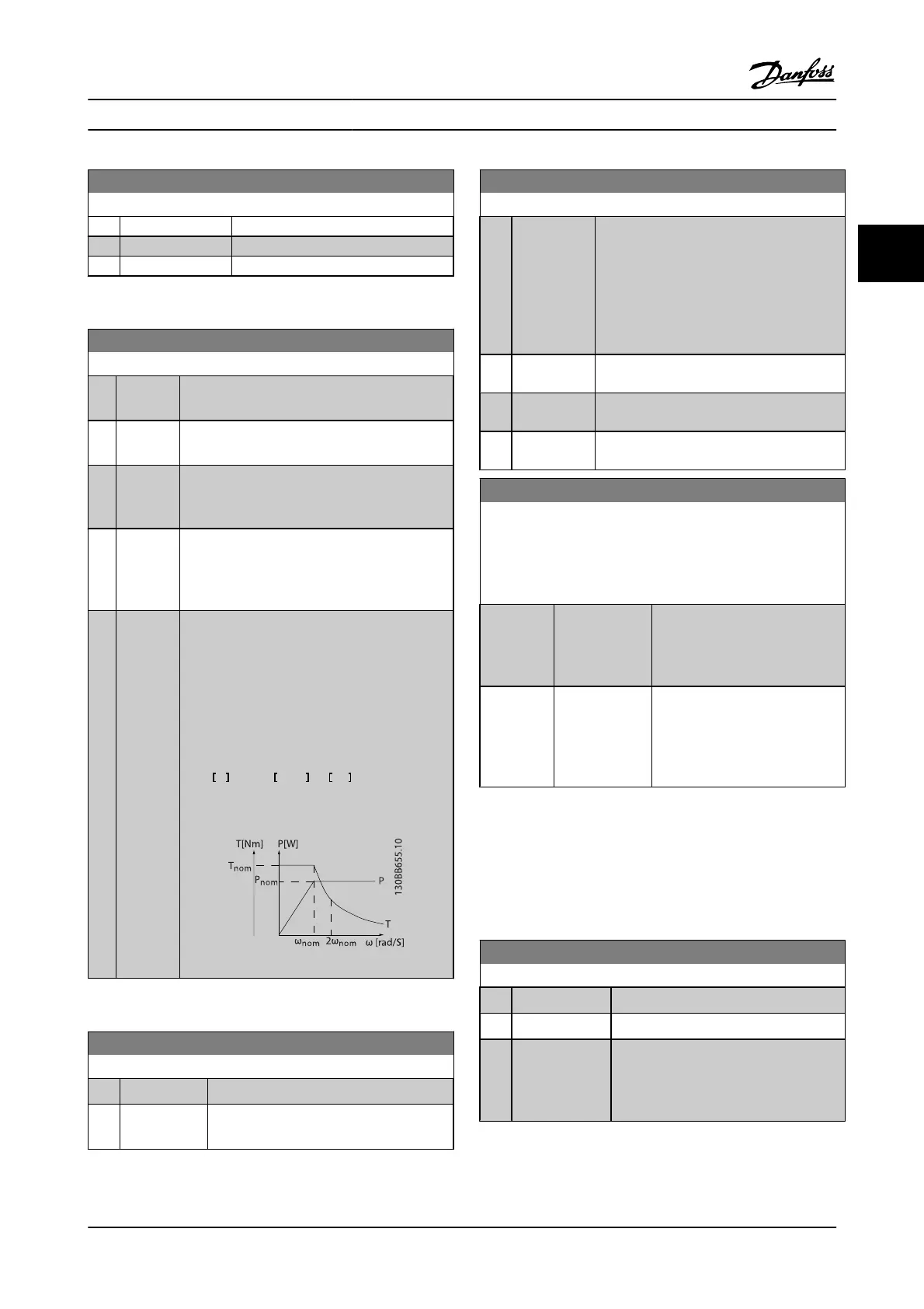
[5] Constant
Power
The function provides a constant power in the
field weakening area.
The torque shape of motor mode is used as a limit
in the generatoric mode. This is done to limit the
power in generatoric mode that otherwise
becomes considerable larger than in motor mode,
due to the high DC link voltage available in
generatoric mode.
P
shaft
W
=
ω
mech
rad /
s
×
T
Nm
This relationship with the constant power is
illustrated in the following graph:
This parameter cannot be adjusted while the motor is
running.
1-04 Overload Mode
Option: Function:
[0]
*
High torque Allows up to 160% over torque.
[1] Normal torque For an oversized motor - allows up to 110%
over torque.
This parameter cannot be adjusted while the motor is
running.
1-05 Local Mode Configuration
Option: Function:
Select which application configuration mode
(1-00 Configuration Mode), i.e., the application
control principle, to use when a Local (LCP)
Reference is active. A local reference can be
active only when 3-13 Reference Site is set to
[0] or [2]. By default, the local reference is
active in hand mode only.
[0] Speed open-
loop
[1] Speed closed-
loop
[2]
*
As mode par
1-00
1-06 Clockwise Direction
This parameter defines the term “Clockwise” corresponding to the
LCP direction arrow. Used for easy change of direction of shaft
rotation without swapping motor wires. (Valid from SW version
5.84)
Option: Function:
[0]
*
Normal Motor shaft will turn in clockwise
direction when adjustable
frequency drive is connected U ->
U; V -> V, and W -> W to motor.
[1] Inverse Motor shaft will turn in counter-
clockwise direction when
adjustable frequency drive is
connected U -> U; V -> V, and W ->
W to motor.
This parameter cannot be changed while the motor is
running.
3.3.2 1-1* Motor Selection
This par. group cannot be adjusted while the motor is
running.
1-10 Motor Construction
Option: Function:
Select the motor construction type.
[0]
*
Asynchron For asynchronous motors.
[1] PM, non salient
SPM
For permanent magnet (PM) motors.
Note that PM motors are divided into two
groups, with either surface mounted (non-
salient) or interior (salient) magnets.
Motor construction can either be asynchronous or
permanent magnet (PM) motor.
Parameter Descriptions FC 300 Programming Guide
MG.33.MA.22 - VLT
®
is a registered Danfoss trademark 3-13
3

 Loading...


