2-11 Brake Resistor (ohm)
Range: Function:
Application
dependent
*
[Application
dependant]
Set the brake resistor value in
Ohms. This value is used for
monitoring the power to the brake
resistor in 2-13 Brake Power
Monitoring. This parameter is only
active in adjustable frequency
drives with an integral dynamic
brake.
Use this parameter for values
without decimals. For a selection
with two decimals, use 30-81 Brake
Resistor (ohm).
2-12 Brake Power Limit (kW)
Range: Function:
Application
dependent
*
[Application
dependant]
Par. 2-12 is the expected average
power dissipated in the brake resistor
over a period of 120s. It is used as the
monitoring limit for par. 16-33 Brake
energy/ 2 min and thereby specifies
when a warning/ alarm is to be given.
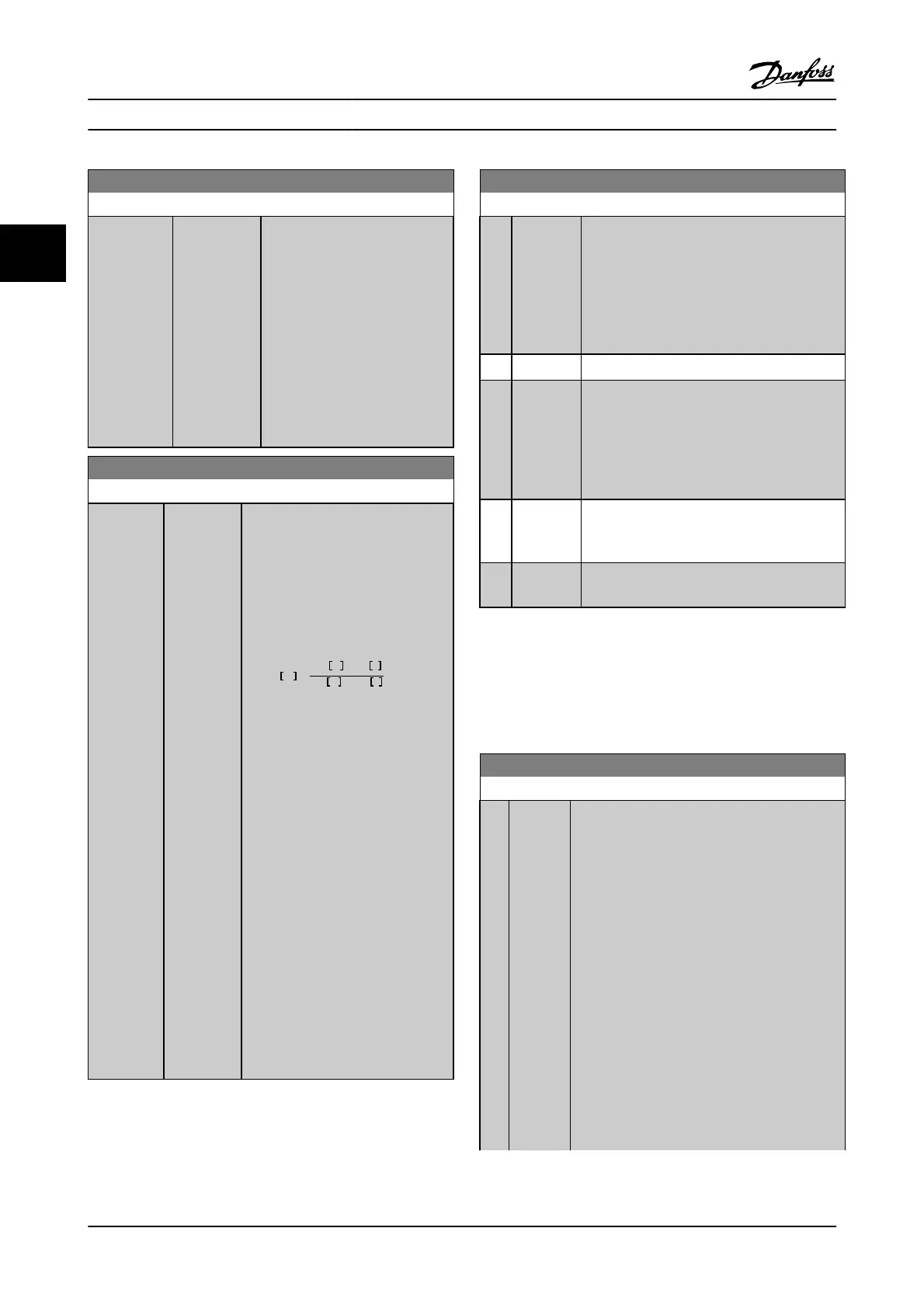
To calculate par. 2-12, the following
formula can be used.
P
br,avg
W
=
U
br
2
V
×
t
br
s
R
br
Ω
×
T
br
s
P
br,avg
is the average power dissipated
in the brake resistor, R
br
is the
resistance of the brake resistor. t
br
is
the active breaking time within the
120 s period, T
br
.
U
br
is the DC voltage where the brake
resistor is active. This depends on the
unit as follows:
T2 units: 390 V
T4 units: 778 V
T5 units: 810 V
T6 units: 943 V / 1099 V for D – F
frames
T7 units: 1099 V
If R
br
is not known or if T
br
is different
from 120s, the practical approach is to
run the brake application, readout par.
16-33 and then enter this + 20% in
par. 2-12.
2-13 Brake Power Monitoring
Option: Function:
This parameter is only active in adjustable
frequency drives with an integral dynamic brake.
This parameter enables monitoring of the power
to the brake resistor. The power is calculated on
the basis of the resistance (2-11 Brake Resistor
(ohm)), the DC-link voltage, and the resistor duty
time.
[0]
*
Off No brake power monitoring required.
[1] Warning Activates a warning on the display when the
power transmitted over 120 s exceeds 100% of
the monitoring limit (2-12 Brake Power Limit
(kW)).
The warning disappears when the transmitted
power falls below 80% of the monitoring limit.
[2] Trip Trips adjustable frequency drive and displays an
alarm when the calculated power exceeds 100%
of the monitoring limit.
[3] Warning
and trip
Activates both of the above, including warning,
trip and alarm.
If power monitoring is set to Off [0] or Warning [1], the brake
function remains active, even if the monitoring limit is
exceeded. This may lead to thermal overload of the resistor.
It is also possible to generate a warning via a relay/digital
output. The measuring accuracy of the power monitoring
depends on the accuracy of the resistance of the resistor
(better than ± 20%).
2-15 Brake Check
Option: Function:
Select type of test and monitoring function to
check the connection to the brake resistor, or
whether a brake resistor is present, and then
display a warning or an alarm in the event of a
fault.
NOTE!
The brake resistor disconnection function is
tested during power-up. However, the brake
IGBT test is performed when there is no
braking. A warning or trip disconnects the
brake function.
The testing sequence is as follows:
1. The DC link ripple amplitude is measured
for 300 ms without braking.
2. The DC link ripple amplitude is measured
for 300 ms with the brake turned on.
Parameter Descriptions FC 300 Programming Guide
3-28 MG.33.MA.22 - VLT
®
is a registered Danfoss trademark
3

 Loading...


