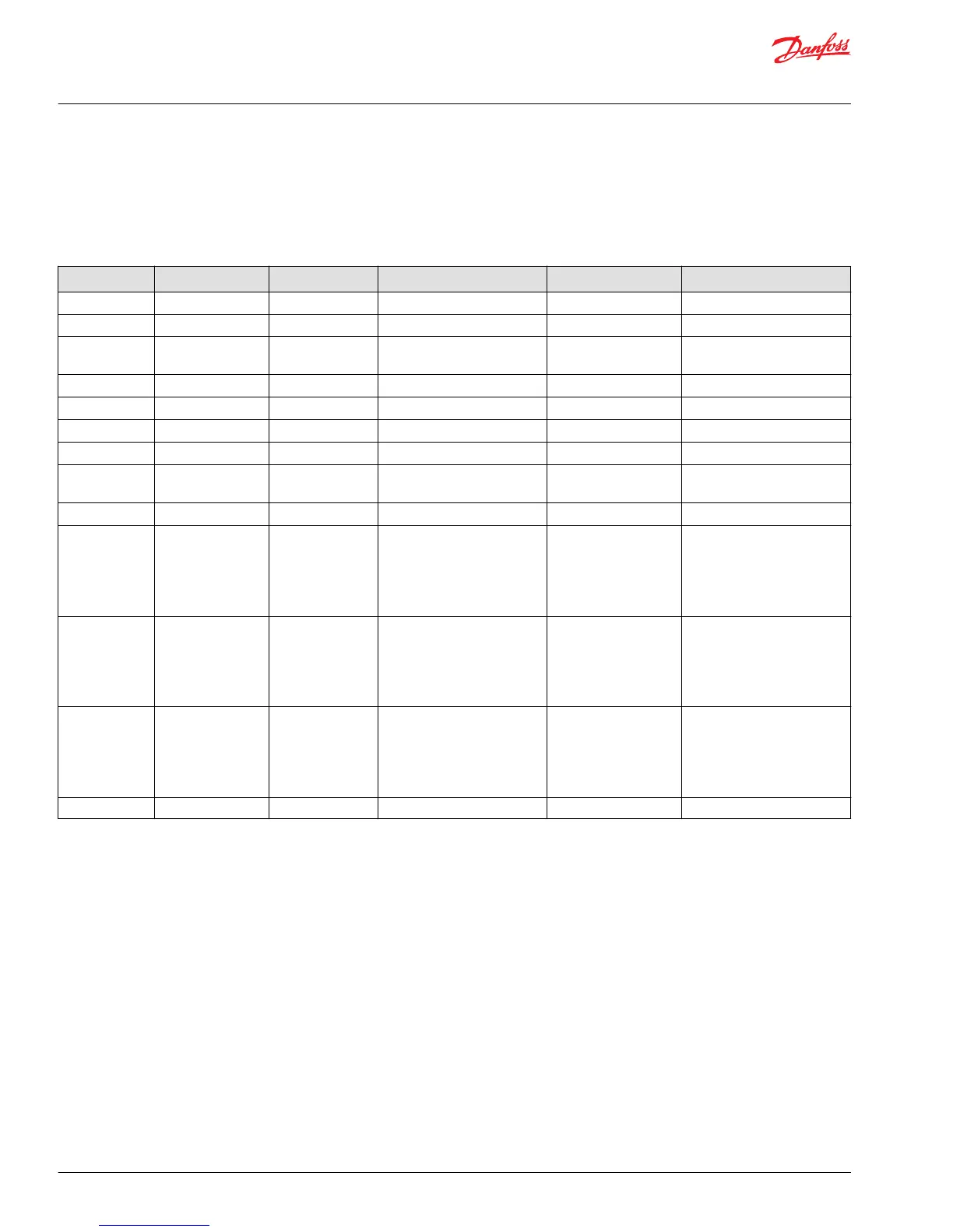
Port Locations and Gauge Installation
The following table and drawing show the port locations and gauge sizes needed. When testing system
pressures, calibrate pressure gauges frequently to ensure accuracy. Use snubbers to protect gauges.
Port Information
Port identifier Port size Wrench size Reading Gauge size, bar [psi] Displacement
L1, L3 7/8-14 UNF 2B 3/8 internal hex Case drain 10 [100] 069/078
L2, L4 1 1/16-12 UNF 2B 9/16 internal hex Case drain 10 [100] 069/078/089/100
L1, L3 1 1/16-12 UNF 2B 9/16 internal hex Case drain 10 [100] 089/100/115/
130/147/165
L2, L4 1 5/16-12 UNF 2B 5/8 internal hex Case drain 10 [100] 115/130/147/165
MA, MB 9/16-18 UNF 1/4 internal hex System pressure 600 [10,000] 115/130/147/165/210/250
M3 9/16-18 UNF 2B 1/4 internal hex Charge pressure- after filter 50 [1000] 115/130/147/165/210/250
M4, M5 7/16-20 UNF 2B 3/16 internal hex Servo pressure 50 [1000] 115/130/147/165/210/250
M6 9/16-18 UNF 2B 1/4 internal hex Charge pressure - pre
integrated filter
50 [1000] 115/130/147/165/210/250
L2, L4
1 5/8-12 UNF 5/8 internal hex Case drain 10 [100]
210/250
A;B 24.5 mm; M12 x
1.75; 20 min. full
thread depth;
Recommended
screw in depth 1.5 x
thread dia.
System Ports A and B 450 bar,
Split flangeboss per ISO 6162
600 [10,000] 069/078/089/100/115/130
A;B 31.5 mm; M12 x
1.75; 20 min. full
thread depth;
Recommended
screw in depth 1.5 x
thread dia.
System Ports A and B 450 bar,
Split flangeboss per ISO 6162
600 [10,000] 147/165
A;B 38 mm; M12 x 1.75;
20 min. full thread
depth;
Recommended
screw in depth 1.5 x
thread dia.
System Ports A and B 450 bar,
Split flangeboss per ISO 6162
600 [10,000] 210/250
S Charge Pump Inlet N/A
Service Manual
H1 Pumps 069/078, 089/100, 115/130, 147/165, 210/250
Pressure Measurements
24 |
©
Danfoss | May 2018 520L0848 | AX00000087en-US0308