Displacement Limiter Adjustment
If your pump has displacement limiters, you will find them on either servo cover. You can limit forward
and reverse displacement independently.
Displacement limiters are not pre-set by the factory. We install them as far as possible without contacting
the servo piston. Limiting displacement requires clockwise adjustment of the limiting screw.
Caution
Before adjusting the displacement limiter, mark the position of the servo cylinder. Be sure the servo
cylinder does not turn when setting the displacement limiter locknut.
1. Loosen the lockingnut.
2. Rotate the adjusting screw to achieve the desired maximum displacement. Set the adjusting screw
against the servo piston by feel before counting turns. Refer to the table below for change per turn.
Clockwise rotation decreases displacement, counterclockwise rotation increases it. Adjustment is
possible from zero to maximum.
3. After establishing the desired maximum displacement setting, hold the adjusting screw while
torquing the locknut to the value in the table below.
4. Test operation of the vehicle/machine to verify proper maximum speed of vehicle/work function.
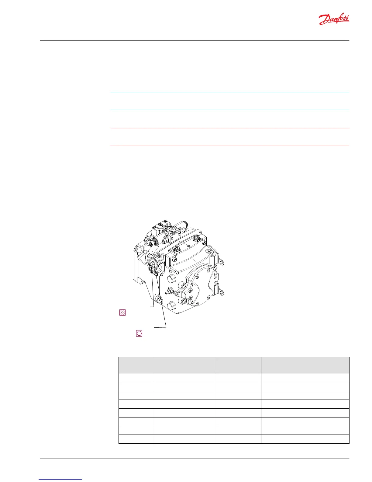
Displacement Limiter Adjustment
P104 469E
Limiting Screw
Locknut
(see table)
(see table)
Displacement Limiter Adjustment Data
Displacement Locknut wrench size and
torque
Adjusting screw
wrench size
Approximate displacement change per
revolution of adjusting screw
069 13 mm - 24 N•m [18 lbf-ft] 4 mm 6.0 cm
3
/turn [0.366 in
3
/turn]
078 13 mm - 24 N•m [18 lbf-ft] 4 mm 7.4 cm
3
/turn [0.452 in
3
/turn]
089 17 mm - 48 N•m [35 lbf-ft] 5 mm 9.3 cm
3
/turn [0.57 in
3
/turn]
100 17 mm - 48 N•m [35 lbf-ft] 5 mm 10.7 cm
3
/turn [0.65 in
3
/turn]
115 22 mm - 80 N•m [59 lbf-ft] 6 mm 10.8 cm
3
/turn [0.66 in
3
/turn]
130 22 mm - 80 N•m [59 lbf-ft] 6 mm 12.2 cm
3
/turn [0.745 in
3
/turn]
147 22 mm - 80 N•m [59 lbf-ft] 6 mm 12.4 cm
3
/turn [0.757 in
3
/turn]
165 22 mm - 80 N•m [59 lbf-ft] 6 mm 13.9 cm
3
/turn [0.848 in
3
/turn]
Service Manual
H1 Pumps 069/078, 089/100, 115/130, 147/165, 210/250
Adjustments
©
Danfoss | May 2018 520L0848 | AX00000087en-US0308 | 35