Pump setup
1. Attach a 50 bar [1000 psi] gauge to each servo pressure port M4 and M5.
2. Attach a 600 bar [10 000 psi] gauge to each system pressure port (MA and MB).
3. Remove servo cylinder locking screws (E350) and plates (E300) from both sides of the pump.
4. Disconnect the control solenoids from the vehicle wiring harness.
5. If using a PWM signal to set mechanical neutral, connect the control solenoids C1 and C2 to the signal
source. Ensure the source supplies no current to the solenoids until required in the following
procedure.
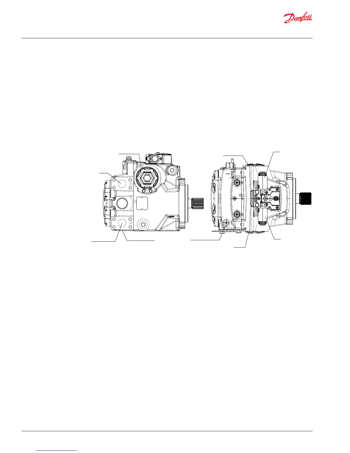
The figure below shows the locations of sysem and gage ports you use when adjusting the servo neutral
postion.
System Pressure Gage Port Locations
Service Manual
H1 Pumps 069/078, 089/100, 115/130, 147/165, 210/250
Adjustments
38 |
©
Danfoss | May 2018 520L0848 | AX00000087en-US0308