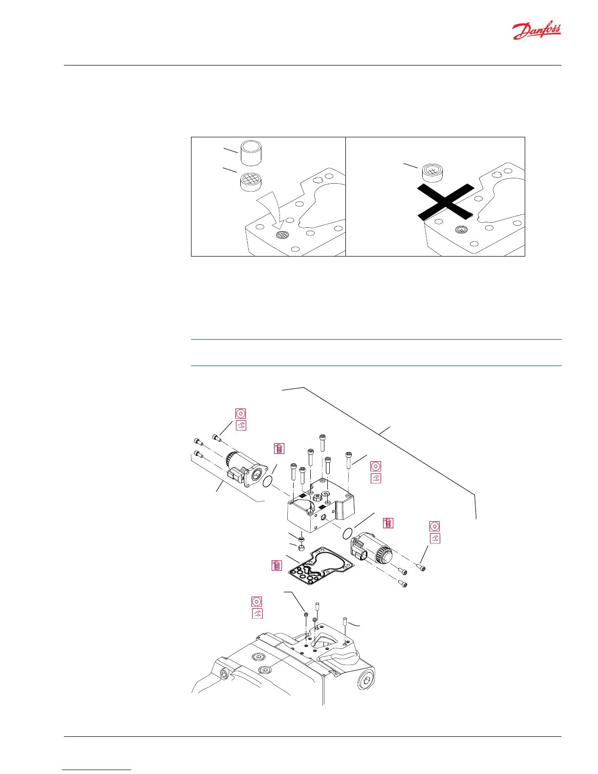
2. If you removed screen (D084), install a new one. Install with the mesh facing outward (see drawing).
Install retaining ring (D098).
3. If previously removed, install orifices (F100) using a 3 mm internal hex wrench. Torque to 2.5 N•m [1.8
lbf•ft].
4. Install the control module and six cap screws (D250).
5. Using a 5 mm internal hex wrench, torque the cap screws (D250) to 13.3 N•m [9.8 lbf•ft].
Remove plug on top of control to ensure the swashplate feedback pin is properly positioned in the
center of the control module when installing control.
Control Module and Solenoid Removal/Installation
Service Manual
H1 Pumps 069/078, 089/100, 115/130, 147/165, 210/250
Minor Repair
©
Danfoss | May 2018 520L0848 | AX00000087en-US0308 | 41