MDC NSS schematic diagram
Automotive Control (AC)
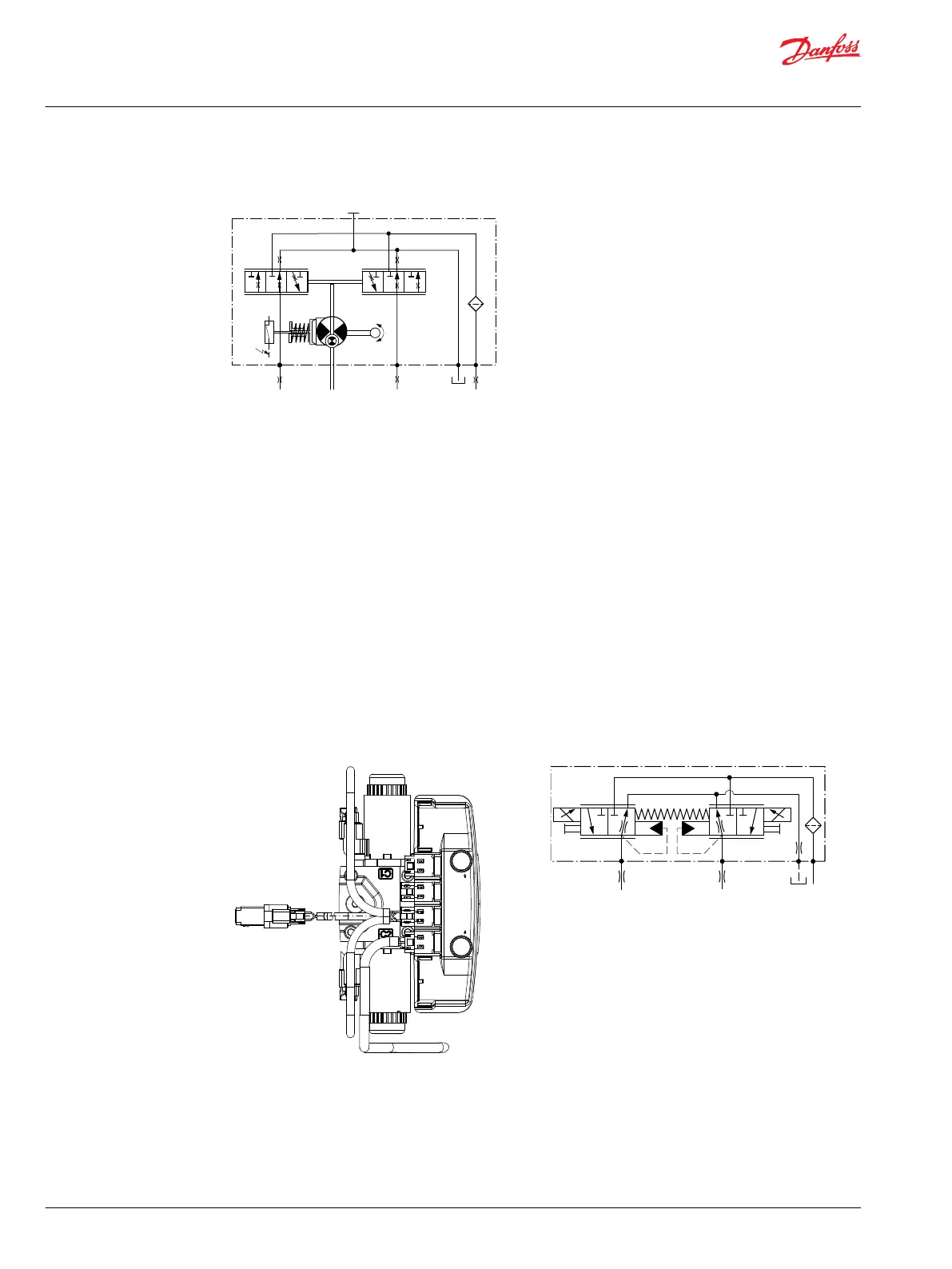
The AC-1 and AC-2 propel transmission system consists of an H1 variable pump, embedded electronic
controller, and service tool configurable PLUS+1® software that allows the customer to completely
optimize vehicle performance. The embedded electronic controller provides an electric input signal
activating one of two solenoids that port charge pressure to either side of the pump servo cylinder. The
AC has no mechanical feedback mechanism but AC-2 is available with an electronic feedback signal for
the swash plate position.
The pump displacement is proportional to the solenoid signal current, but it also depends upon pump
input speed and system pressure. This characteristic also provides a power limiting function by reducing
the pump swash plate angle as system pressure increases. A typical response characteristic is shown in
the accompanying graph.
Under some circumstances, such as contamination, the control spool could stick and cause the pump to
stay at some displacement.
A serviceable 125 µm screen is located in the supply line immediately before the control porting spool.
Automotive Control (AC)
P003 544
CAN PPC
PSC
PPU
CC2
CC1
WARRANTY VOID IF REMOVED
CC3
Automotive Control (AC) schematic
Basic Information
H1 Axial Piston Pumps, Single and Tandem
Operation
12 |
©
Danfoss | April 2017 11062168 | BC00000057en-US0602

 Loading...


