Determination of nominal pump sizes
Generally, the sizing process is initiated by an evaluation of the machine system to determine the
required motor speed and torque to perform the necessary work function.
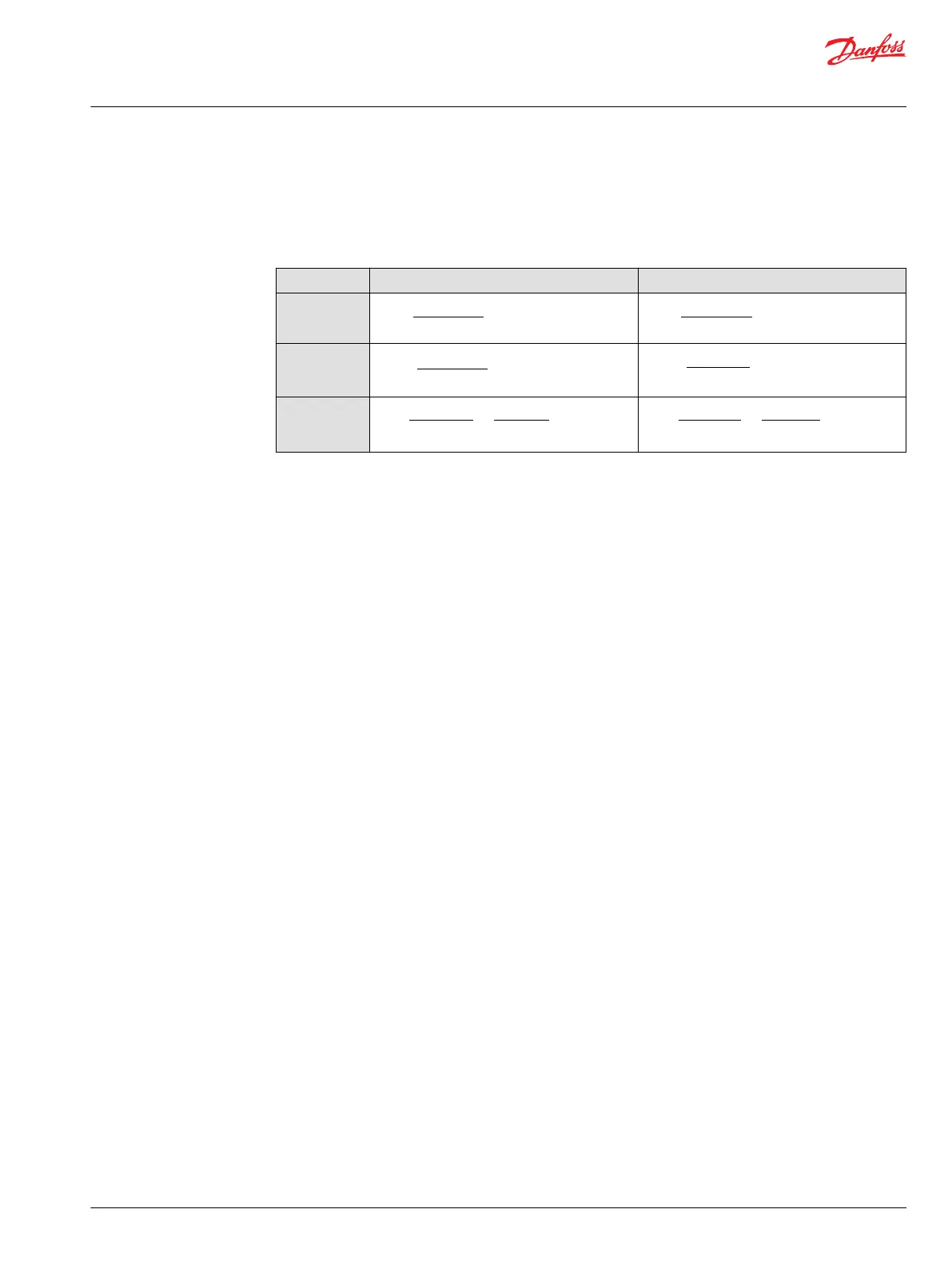
Use the following formulae to determine the nominal pump size for a specific application:
Metric System Inch System
Output flow
Q
e
=
1000
V
g
• n • η
v
(l/min)
Q
e
=
231
(US gal/min)
V
g
• n • η
v
Input torque
M
e
=
20 • π • η
m
V
g
• ∆p
(N•m)
M
e
=
2 • π • η
m
V
g
• ∆p
(lbf•in)
Input power
P
e
=
30 000
η
t
• n • p
=
600 •
Q
e
• ∆p
M
e
(kW)
P
e
=
198 000
η
t
• n • p
=
1714 •
Q
e
• ∆p
M
e
(hp)
Variables:
Vg = Displacement per rev.
p
HP
= High pressure
p
NP
= Low pressure
∆p = p
HP
– p
NP
n = Input speed
η
v
= Volumetric efficiency
η
m
= Mechanical (torque) efficiency
η
t
= Overall efficiency (η
v
• η
m
)
SI units [US units]:
cm
3
/rev [in
3
/rev]
bar [psi]
bar [psi]
bar [psi]
min
-1
(rpm)
First, the motor is sized to transmit the maximum required torque. The pump is then selected as a flow
source to achieve the maximum motor speed. For more details see Selection of Drive Line Components,
BLN-9885.
Basic Information
H1 Axial Piston Pumps, Single and Tandem
System design parameters
©
Danfoss | April 2017 11062168 | BC00000057en-US0602 | 37

 Loading...


