CAUTION
Remote filter heads without bypass and poor plumbing design can encounter excessive pressure drops
that can lead to charge pump damage in addition to contaminants being forced through the filter media
and into the transmission loop.
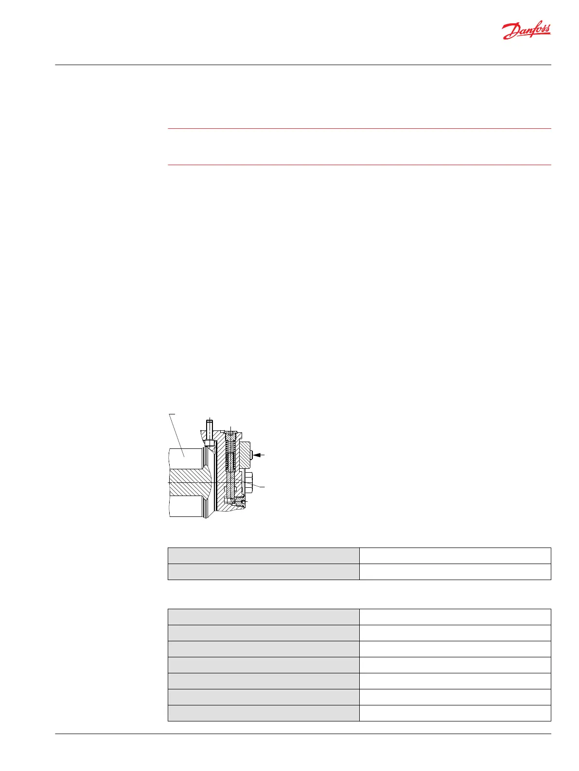
Integral charge pressure filtration
The H1 integral pressure filter head is designed with a filter bypass valve and noncontacting bypass
sensor. The pressure differential acting on the filter element also acts on a spring biased bypass spool.
This spool is designed with a magnetic area. When a certain spool position is reached, the magnet closes
a switch in the bypass sensor which allows R2 to be in parallel with R1. This occurs without any
mechanical contact between the spool and the bypass sensor.
The position of the bypass spool is indicated by the change in the measured sensor resistance. The
change in resistance occurs when R2 is switched in and out of the circuit.
When the filter is not being bypassed, the nominal measured resistance is 510 Ω. When the switch is
closed, the nominal measured resistance is 122 Ω.
The bypass spool is designed so the bypass sensor switch will be closed before oil bypasses the filter
element. This gives the machine operator an indication that the filter is very close to bypassing and a
filter replacement is required.
For cold start conditions, it is typical that the filter may bypass for a short amount of time while the oil is
warming up. At normal operating oil temperatures, a system that does not yet need a filter replacement
will operate in the non-bypass mode. The addition of an oil temperature sensor and additional control
logic, is recommended to properly determine if a filter replacement is required.
Integral filter head with filter bypass sensors
Bypass spool
Filter
bypass sensor
Filter
element
P003 359E
Technical data, pressures
Filter bypass sensor switch closure ∆p
3.7 - 5.1 bar [54 - 74 psi]
Bypass valve ∆p
5.6 ± 0.9 bar [80 ± 13 psi]
Technical data, electric
Max. voltage
48 V
Max. power
0.6 W
Switch open
510 Ω
Switch closed
122 Ω
Resistor tolerance
1 %
Temperature range
-20 ÷ +100 °C [-4 ÷ +212 °F]
IP Rating (IEC 60 529) + DIN 40 050
IP 69K part 9 with mating connector
Basic Information
H1 Axial Piston Pumps, Single and Tandem
System design parameters
©
Danfoss | April 2017 11062168 | BC00000057en-US0602 | 27

 Loading...


