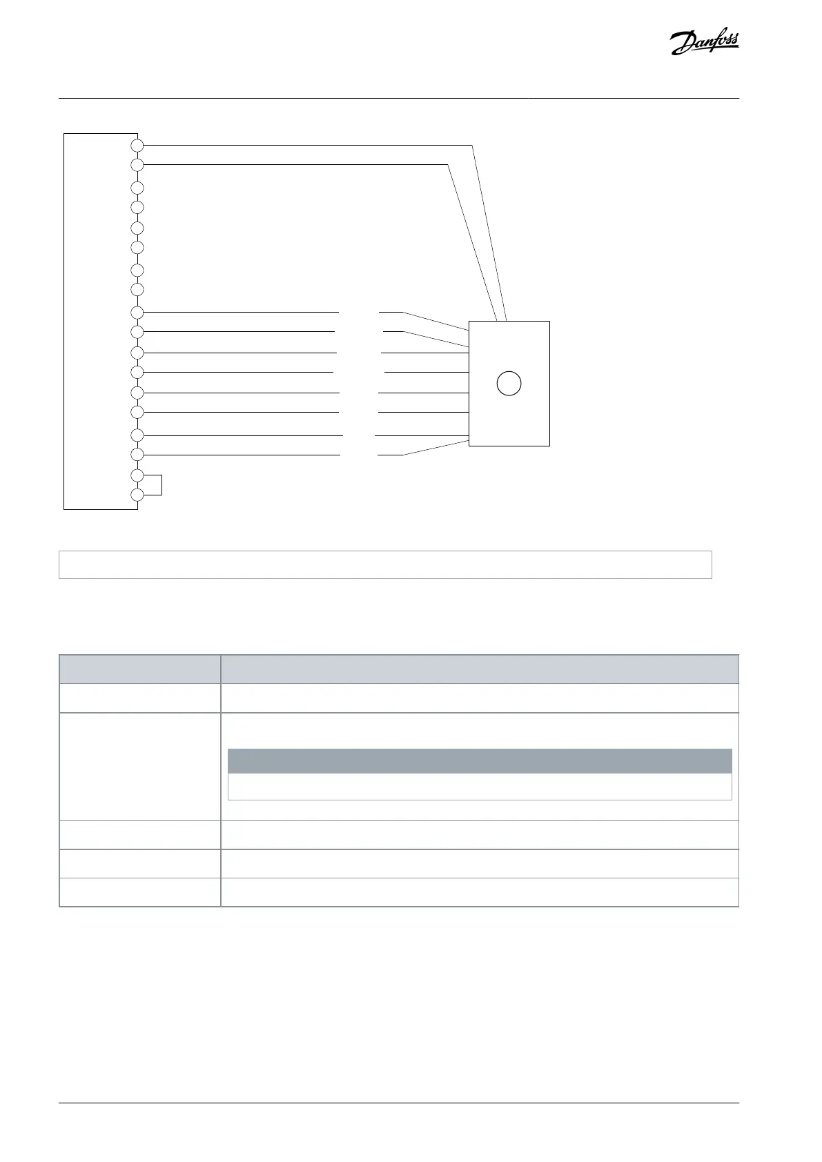
7
3
5
2
1
9
8
6
4
13
11
10
16
14
12
18
A+/+SIN
A–/REFSIN
B+/+COS
B–/REFCOS
Clock+
Clock–
Data+
Data–
1
Illustration 15: Wiring Configuration for SSI Encoder with Incremental or SinCos Track
5.5.10 EnDat Encoder
Absolute position is read from the encoder and used to set the actual position after power-up.
Table 17: Parameters for EnDat Encoder
9.4.1 Interface configuration
9.4.4 Encoder Supply Voltage
Set the appropriate supply voltage.
N O T I C E
Voltage can be up to 24 V. Setting the voltage too high can damage the connected encoder.
9.6.1 Singleturn Resolution
Set the number of bits used for 1 revolution.
9.6.2 Multiturn Resolution
Set the number of bits used for revolution count.
Set the rate for the clock signal according to the encoder specifications.
AQ390830267692en-000601 / 136R027328 | Danfoss A/S © 2023.06
Encoder/Resolver Installation and
Configuration
Functional Extension Options
Operating Guide