e30bj666.10
17
15
7
3
5
2
1
9
8
6
4
13
11
10
16
14
12
18
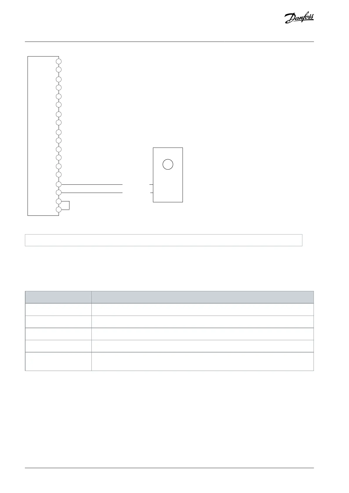
Data/supply+
Data/supply–
1
Illustration 19: Wiring Configuration for HIPERFACE DSL
®
Encoder
5.5.14 HIPERFACE DSL® and Incremental (TTL or HTL) Encoder
This example shows the connection of a HIPERFACE DSL® encoder on D as channel/feedback device 1 and a 2-track incremental
encoder on A and B as channel/feedback device 2. The HIPERFACE DSL® encoder supply (pin 17) is inactive so the incremental en-
coder must be supplied by an external power source.
Table 21: Parameters for HIPERFACE DSL® and Incremental (TTL or HTL) Encoder
9.4.1 Interface configuration
Select [27] Hiperface DSL D + 2 track incremental A,B
9.4.4 Encoder Supply Voltage
Set the appropriate voltage.
9.5.2 Resolution Channnel 2
Set the resolution of the incremental encoder connected to A and B in pulses per revolution.
9.6.1 Singleturn Resolution
Set the number of bits used for 1 revolution of the connected HIPERFACE DSL® encoder.
9.6.2 Multiturn Resolution
Set the number of bits used for counting the revolutions of the connected HIPERFACE DSL® encod-
er.
AQ390830267692en-000601 / 136R027332 | Danfoss A/S © 2023.06
Encoder/Resolver Installation and
Configuration
Functional Extension Options
Operating Guide