1
9
8
6
4
13
11
10
16
14
12
18
Clock+
Clock–
Data+
Data–
1
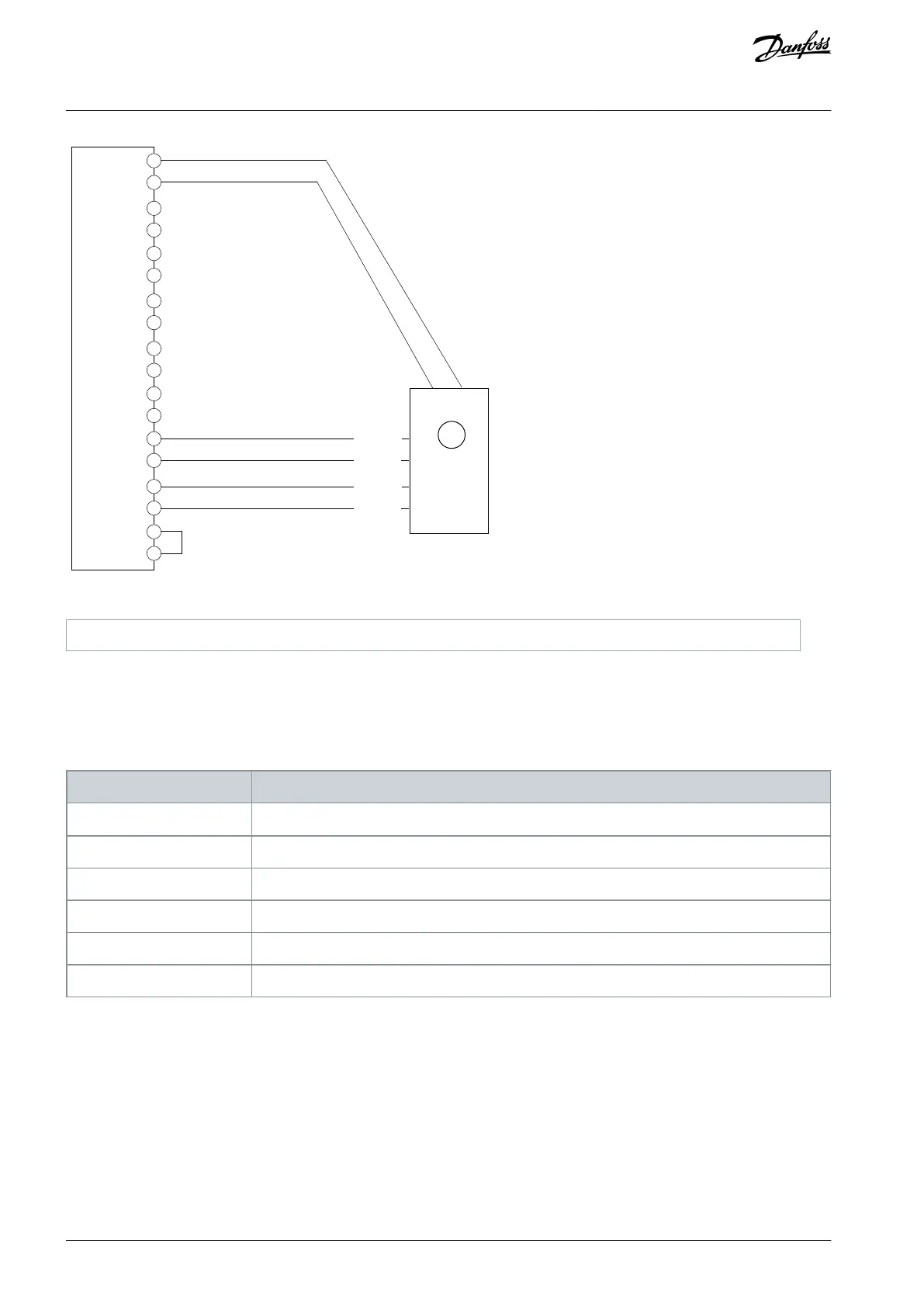
Illustration 21: Wiring Configuration for 2-Track BiSS Encoder
5.5.16 BiSS and Incremental (TTL or HTL) Encoder
This example shows the connection of a BiSS encoder on Z and D as channel/feedback device 1 and a 2 track incremental encoder
on A and B as channel/feedback device 2. An external supply might be needed it power requirement exceeds the maximum power
of the encoder supply (pin 17), or if the 2 encoders require different supply voltages.
Table 23: Parameters for BiSS and Incremental (TTL or HTL) Encoder
9.4.1 Interface Configuration
Select [30] BiSS Z,D + 2 track incremental A,B.
9.4.4 Encoder Supply Voltage
Set the appropriate voltage.
9.5.2 Resolution Channel 2
Set the resolution of the incremental encoder connected to A and B in pulses per revolution.
9.6.1 Singleturn Resolution
Set the number of bits used for 1 revolution of the connected BiSS encoder.
9.6.2 Multiturn Resolution
Set the number of bits used for counting the revolutions of the connected BiSS encoder.
9.6.5 BiSS/SSI Clock Rate
Select the clock rate according to the encoder specifications.
AQ390830267692en-000601 / 136R027334 | Danfoss A/S © 2023.06
Encoder/Resolver Installation and
Configuration
Functional Extension Options
Operating Guide