EasyManua.ls Logo

Danfoss KP Series User Manual

Danfoss KP Series
4 pages
To Next Page IconTo Next Page
To Previous Page IconTo Previous Page
Page #3 background image
© Danfoss A/S RI.5D.A2.22 DKRCC.PI.C0A.A1.22-520H2749 3
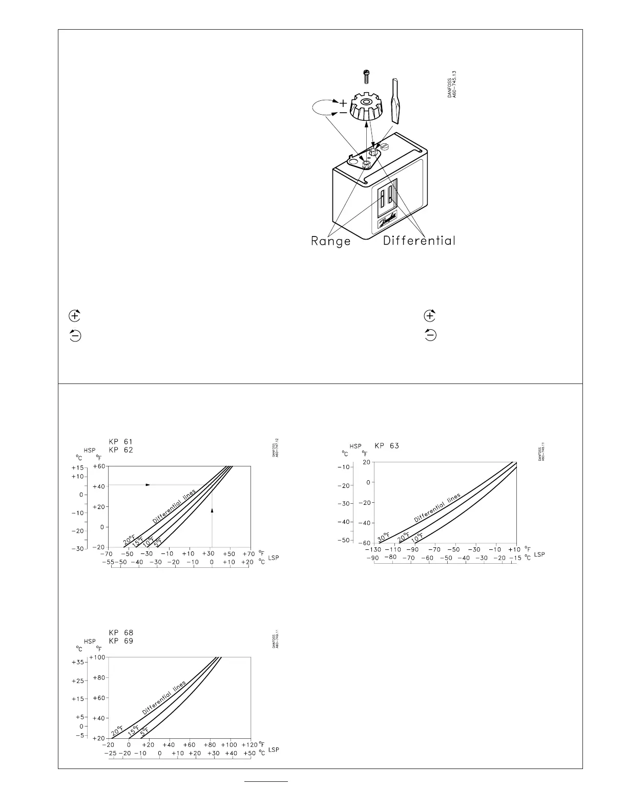
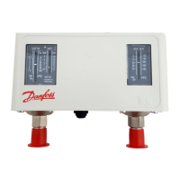
Adjustment spindles location
Note!
Remove lockplate before thermostat
adjustment. Replace lockplate after
adjustment (if desired).
RANGE DIFFERENTIAL
See printed instruction on top of control See printed instruction on top of control
increase temp. (warmer): turn CW Increase: turn CW
decrease temp. (colder): turn CCW decrease: turn CCW
(use adjustment knob) (use adjustment knob or screwdriver)
Determination of di erential
For KP w/ vapor charge and auto. reset (KP 61, KP 62, KP 63, KP 68, KP 69): Use graphs to determine correct di erential
Example:
HSP = +45°F (+5.6°C) => DIFF (from graph):
LSP = +32°F (0°C 13°F (7.2°C) (value which has to be
set on di . scale).
For KP w/ adsorption charge (KP 71, KP 73, KP 75, KP 77, KP 79, KP 81):
The di erential will be HSP less LSP
Example: HSP LSP = DIFF.
45°F 35°F = 10°F
(7°C) (5°C) (2°C)
Note:
(Load Option A) (Load Option B)
CUT-IN = HSP or CUT-IN = LSP
CUT-OUT = LSP CUT-OUT = HSP
See “Wiring
Question and Answer IconNeed help?

Do you have a question about the Danfoss KP Series and is the answer not in the manual?

Danfoss KP Series Specifications

General IconGeneral
DimensionsVaries by model
WeightVaries by model
Contact functionSPDT
Reset functionAutomatic or Manual
MediaAir, water, oil
ApprovalsEN
DifferentialVaries by model
Connection Size1/2"
Control RangeVaries by model
AccuracyVaries by model
Power SupplyNone (mechanical thermostat)
Switching Current16A (resistive load)
Protection ClassIP54
MountingVaries by model

Summary

Pressure Controls KP 61-81

Control Types and Bulb Specifications

Details different control types (auto/manual reset) and sensor bulb types (vapor/adsorption charge).

Installation and Environmental Requirements

Covers mounting, enclosure (IP33), cable entry, and ambient temperature limits.

Maximum Bulb Temperature Limits

Specifies the maximum allowable temperatures for the sensor bulbs based on model.

Evaporator Capillary Tube Length

Defines minimum required lengths for capillary tubes connected to the evaporator.

Wiring and Load Options

Wiring Connections and Safety

Guidelines for safe wiring practices, terminal block usage, and load ratings.

Load Option A vs. Load Option B

Explains how terminals 1-4 and 1-2 function for temperature rise/drop in different load options.

Manual Tripping and Reset

Manual Tripping Procedure

Instructions for testing electrical contacts by manually tripping the control.

Manual Reset Procedure

Steps to resume operation after a safety cut-out, including reset knob usage.

Adjustment Spindles and Differential Setting

Adjustment Spindle Location and Usage

Identifies range and differential adjustment spindles and their operation (CW/CCW).

Determining Differential

Utilizes graphs to determine the correct differential for vapor charge controls.

Differential for Adsorption Controls

Explains how to calculate differential for adsorption charge controls (KP 71-81).

Setting High and Low Set Points

Setting for Auto Reset Controls

Procedure to adjust range (HSP) and differential spindles for auto reset models.

Setting for Manual Reset Controls

Procedure to adjust range (LSP) for manual reset models where differential is fixed.

Hand Switch Operation

Details the function of the hand switch in auto and micro-stop positions.

Related product manuals