EasyManua.ls Logo

Danfoss KP 61 User Manual

Danfoss KP 61
4 pages
To Next Page IconTo Next Page
Page #1 background imageLoading...
Page #1 background image
t ≥ t + 2 °C (3.5 °F)
t
t
Danfoss
60-730.15
Varpor charge
KP 61, KP 62, KP 63 Max.
KP 68, KP 69 : 120 °C (250 °F)
KP 71, KP 73: 80 ° C (175 °F)
KP 75 : 110 °C (230 °F)
KP 77 : 130 °C (265 °F)
KP 79 : 150 °C (300 °F)
KP 81 : 200 °C (390 °F)
Varpor charge
Adsorption charge
Danfoss
60-731.14
Drip proof IP30
(EN 60529)
10 – 32 UNC
Danfoss
60-735.12
max. / in.
(3 mm)
Cable entry
/ in. int.
thread accepts
/ in. NPT or NPS
Danfoss
60-733.12
min. -40 °C (-40 ° F)
max. 65 °C (150 °F)
Danfoss
60-732.12
Installation guide
Thermostat
Types KP 61 - KP 81
© Danfoss A/S (AC-MCI / jmn), 2013-11 DKRCC.PI.CA0.C1.22 / 520H8304 1
060R9748
060R9748
KP 61, KP 62, KP 63, KP 68, KP 69 vapor charge
KP 71, KP 73, KP 75, KP 77, KP 79, KP 81 adsorption charge (cross ambient)
Auto reset Manual reset Auto reset
(w/o hand knob) w/ hand switch
Types Bulb types
Varpor charge Adsorption charge
Mounting requirement Max. bulb temperature Ambient temperatures
Enclosure
Cable entry Required cap. tube length on evaporator
80 in. cap. tube: min. 16 in.
196 in. cap. tube: min. 22 in.
CAUTION: The mounting panel must be
plane to avoid damage of control.
Question and Answer IconNeed help?

Do you have a question about the Danfoss KP 61 and is the answer not in the manual?

Danfoss KP 61 Specifications

General IconGeneral
BrandDanfoss
ModelKP 61
CategoryThermostat
LanguageEnglish

Summary

Installation Guide for Thermostats KP 61-KP 81

Thermostat Types and Specifications

Covers different thermostat types including vapor charge and adsorption charge variants.

Mounting and Installation Requirements

Details on mounting procedures, enclosure types, and cable entry specifications.

Temperature and Environmental Considerations

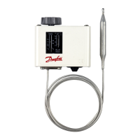
Information on bulb types, max bulb temperature, ambient temperatures, and tube length.

Wiring and Operation Modes

Wiring Configurations and Examples

Explains the two load options for wiring thermostats, including circuit diagrams.

Contact Load Ratings and Manual Tripping

Lists contact load ratings and describes manual tripping for electrical contact testing.

Manual Reset Functionality

Details how to use the manual reset feature for thermostats after safety cut-out.

Adjustment and Differential Settings

Adjustment Spindle Locations

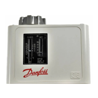
Describes the location and function of range and differential adjustment spindles.

Determining Differential Settings

Provides graphs and examples for setting the differential for various thermostat types.

Thermostat Setting Procedures

Setting for Auto Reset Thermostats

Instructions for setting range and differential for auto reset thermostats.

Setting for Manual Reset Thermostats

Instructions for setting range for manual reset thermostats with fixed differential.

Operation of Hand Switch

Explains the function of the hand switch and its contact positions.

Related product manuals