Do you have a question about the Danfoss KP Series and is the answer not in the manual?
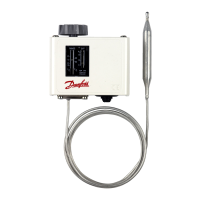
Details different control types (auto/manual reset) and sensor bulb types (vapor/adsorption charge).
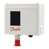
Covers mounting, enclosure (IP33), cable entry, and ambient temperature limits.
Specifies the maximum allowable temperatures for the sensor bulbs based on model.
Defines minimum required lengths for capillary tubes connected to the evaporator.
Guidelines for safe wiring practices, terminal block usage, and load ratings.
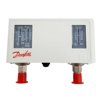
Explains how terminals 1-4 and 1-2 function for temperature rise/drop in different load options.
Instructions for testing electrical contacts by manually tripping the control.
Steps to resume operation after a safety cut-out, including reset knob usage.
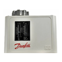
Identifies range and differential adjustment spindles and their operation (CW/CCW).
Utilizes graphs to determine the correct differential for vapor charge controls.
Explains how to calculate differential for adsorption charge controls (KP 71-81).
Procedure to adjust range (HSP) and differential spindles for auto reset models.
Procedure to adjust range (LSP) for manual reset models where differential is fixed.
Details the function of the hand switch in auto and micro-stop positions.
| Dimensions | Varies by model |
|---|---|
| Weight | Varies by model |
| Contact function | SPDT |
| Reset function | Automatic or Manual |
| Media | Air, water, oil |
| Approvals | EN |
| Differential | Varies by model |
| Connection Size | 1/2" |
| Control Range | Varies by model |
| Accuracy | Varies by model |
| Power Supply | None (mechanical thermostat) |
| Switching Current | 16A (resistive load) |
| Protection Class | IP54 |
| Mounting | Varies by model |