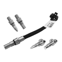
Technical Information KPP PPU
11029257 • Rev BB • July 201314
Product Installation
Refer to Installation Diagrams, page 16, regarding these procedures.
Procedure A
Non-directional KPP at end models. Models included: KPPG12XXX, KPPG16XXX. Installation steps:
1. Turn in (CW) by hand until bottom end gently touches the speed ring.
2. Back out (CCW) 1/2 to 3/4 turn.
3. Using a 1/2 inch wrench to hold the KPP, torque the lock nut to 13 N•m [10 lbf•ft] with an 11/16 inch
hex wrench.
Procedures for Flat End and
Conical End Models
Procedure B:
Directional KPP at end models. Models included: KPPG13XXX, KPPG14XXX, KPPG15XXX, KPPG18XXX.
Installation steps:
1. Turn in (CW) by hand until bottom end gently touches the speed ring.
2. Back out (CCW) 1/4 turn. Continue backing out until the ats are 22° (most open-end wrenches
have a 22° oset) either side of pump or motor shaft center line (20° to 30° is acceptable). Do not
back out the KPP more than 3/4 of a turn from touching.
3. Using the 1/2 inch wrench to hold the KPP, torque the lock nut to 13 N•m [10 lbf•ft] with an 11/16
inch hex wrench.
4. Special KPP FLAT END models include: KPPG17XXX, KPPG19XXX, KPPG1AXXX. Installation range is
application specic:
5. Turn in (CW) by hand until bottom end gently touches the speed ring.
6. Back out (CCW) 1/4 turn. Continue backing out until the ats are 22° (most open-end wrenches
have a 22° oset) either side of pump or motor shaft center line (acceptable range is determined
per application). Do not back out the KPP more than 3/4 of a turn from touching.
7. Using the 1/2 inch wrench to hold the KPP, torque the lock nut to 13 N•m [10 lbf•ft] with an 11/16
inch hex wrench.

 Loading...