Technical Information KPP PPU
11029257 • Rev BB • July 2013 5
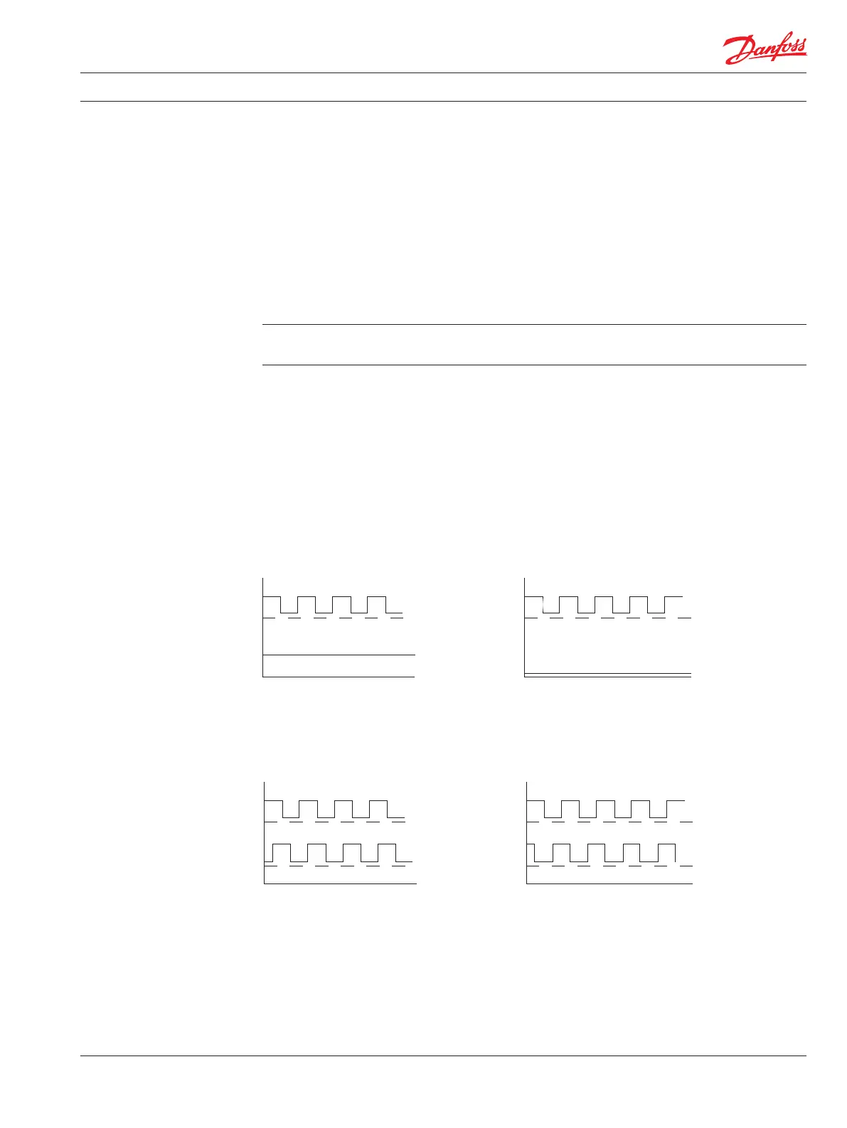
Directional Pulse Train
Theory of Operation
An external source powers the KPP pulse pickup (PPU). It needs a magnetic eld to pass by its Hall
switch(s) to provide a speed signal. The speed ring on the cylinder block has alternately magnetized
north and south segments. For the non-directional PPU (KPPX12X), when a north segment is above
the Hall switch, the switch output voltage is high, and when a south segment is above the switch,
output is low. The digital (on-o-on-o) pulse train feeds to a controller, that interprets its rate of
change as a speed.
The direction-sensing PPU (KPPA13X) uses two Hall sensors mounted side-by-side in the same case.
With proper orientation, the pulse train output from one sensor leads the other sensor by 90°. A logic
circuit decodes the two signals to give a direction indication at the speed output (high or low
depending on direction). For quadrature directional signal, the logic is bypassed and the direction
signal is phase shifted by a nominal of 90° from the signal A. Refer to Directional Pulse Train, on this
page below.
Do not attempt to apply a quadrature output PPU without rst consulting with a
Sauer-Danfoss eld applications engineer for specic application requirements.
The KPPC,D,E models are an improved version of the KPPA12X PPU. It is not necessary to align the ats
on its housing with the speed ring for proper speed readings.
Refer to Typical Speed Control, page 13, as an example of a simple closed-loop speed control
application for the PPU. Connections for a three and four-wire application, refer to Connection
Diagram, page 17.
The KPPXN8Nnn divides the standard signal output by two.
HI
LOW
Speed signal B
Direction D
Clockwise rotation Counter-clockwise rotation
HI
LOW
HI
LOW
HI
LOW
Speed signal B
Direction D
2189
HI
LOW
Clockwise rotation Counter-clockwise rotation
HI
LOW
HI
LOW
HI
LOW
Direction D
Speed signal B
Direction D
Quad Directional Pulse Train