36
MAGFLO
â
Installation of signal
conv.
6. Installation of signal converter
6. Installation of signal
converter
6.1
Integral installation
MAG 5000 and MAG 6000
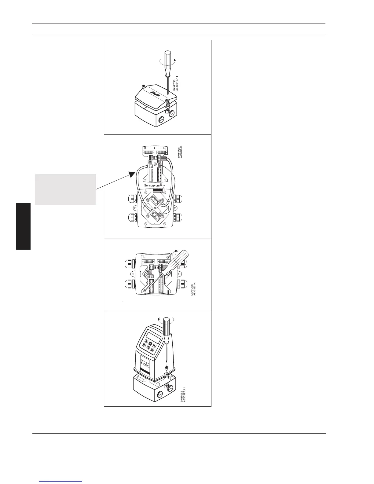
Step 1
Remove and discard the terminal box lid of the
sensor.
Fit the PG 13.5 cable glands for the supply and
output cables.
Step 2
Remove the two black plug assemblies for coil
and electrode cables in the terminal box and
connect them to their corresponding terminal
numbers on the connection board.
Step 3
Connect an earth wire between PE on connec-
tion board and bottom of connection box.
Connect the 2 pin connector and 3 pin connector
as shown.
Note
In earlier version the 3 pin connector was a 5 pin
connector.
Step 4
Mount the connection plate in the terminal box.
The SENSORPROM
®
unit connections will be
established automatically when the connection
plate is mounted in the terminal box.
Note
Check that your connection board lines up with
the SENSORPROM
®
unit, if not, move the
SENSORPROM
®
unit to the other side of the
terminal box.
Step 5
Fit the supply and output cables respectively
and tighten the cable glands to obtain optimum
sealing.
Please refer to the wiring diagram in section 7
for the electrical connections.
Mount the signal converter on the terminal box.
Note
System will not register
flow if black plugs are not
connected to connection
board
 Loading...