19
SYSTEM DESIGN RECOMMENDATIONS
Motor protection
Discharge temperature
protection
Even when the motor windings are
protected against overheating by the
internal motor protection, the com-
pressor discharge gas temperature
could exceed the maximum allowed
value of 135°C when the compres-
sor is operated outside its application
envelope. The most e ective protec-
tion against too high discharge gas
temperature is to mount a discharge
gas thermostat. An accessory kit is
available from Danfoss which includes
Voltage unbalance Operating voltage limits are shown in
the table on page 9. The voltage ap-
plied to motor terminals must lie with-
in these limits during both start-up
and normal operation. The maximum
allowable voltage unbalance is 2%.
Voltage unbalance causes high am-
perage on one or more phases, which
in turn leads to overheating and pos-
sible motor damage.
The voltage unbalance is given by the
following formula:
Cycle rate limit No more than 12 starts per hour (6
when a soft start accessory is used)
are allowed. A higher number would
reduce the service life of the motor-
compressor unit. If necessary, use an
anti-short-cycle timer within the con-
trol circuit.
The system must be designed in a way
that guarantees minimum compressor
running time so as to provide su cient
motor cooling after start-up as well as
proper oil return from the system to
the compressor.
A 5-minute delay between two suc-
cessive compressor starts is being pro-
posed herein, with a 2-minute runtime
after each start and a 3-minute idle
time between each stop and start.
Only during the pump-down cycle
may the compressor run for much
shorter intervals.
Vavg = Mean voltage of phases 1, 2 and 3
V1-2 = Voltage between phases 1 and 2
V1-3 = Voltage between phases 1 and 3
V2-3 = Voltage between phases 2 and 3.
|Vavg - V1-2 |+|Vavg - V1-3 |+|Vavg - V2-3 |
2 xVavg
% voltage unbalance: x 100
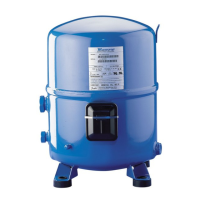
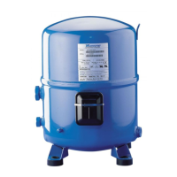
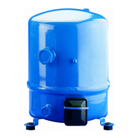
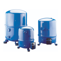
Internal motor protection Maneurop® NTZ compressors have a
built-in motor protection which pro-
tects the motor against overheating,
current overload and locked rotor con-
ditions. Additional external overload
protection is not compulsory but may
still be advisable for alarm function
and to avoid the compressor tripping
on its internal protection.
Further an external safety cut-out can
also de-energise the liquid line sole-
noid valve preventing liquid transfer
from the condenser to the evaporator.
Such function can not be handled by
the built-in motor protector.
For the selection of an external motor
protector the RLA (Rated Load Amps)
values from page 9 can be used.
A thermal overload relay shall be se-
lected to trip at not more than 140% of
the RLA value. A circuit breaker shall be
selected to trip at not more than 125%
of the RLA value. Further requirements
for the external protector are:
z
Over-current protection; the protec-
tor must trip within 2 minutes at 110%
of the Maximum Continuous Current
(MCC). The MCC value is listed in the
table on page 9 and stamped as A-max
on the compressor nameplate.
z
Locked rotor protection; the protec-
tor must trip within 10 seconds on a
start at locked rotor current (LRA)
z
Single phasing protection; the pro-
tector must trip when one of the three
phases fails.
 Loading...