PTC
FU
FU
C1
EC
TH
N
L1
L2
L3
C1
MS
IOL
Comp.
13
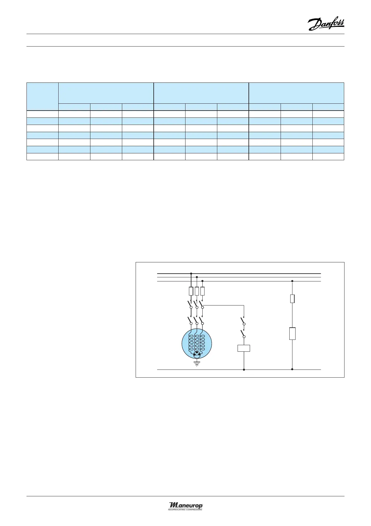
ELECTRICAL CONNECTIONS AND WIRING
Three phase motor
protection and
suggested wiring
diagram
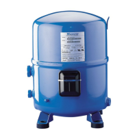
Three phase compressors are inter-
nally protected by a temperature /
current-sensing bimetallic protector,
connected to the neutral point of the
star-connected stator windings. This
internal overload line break protects
the motor against overheating, cur-
rent overload and locked rotor con-
ditions. If the motor were to be over-
loaded and the protector trips, all
3-phases are cut out. It might take up
to several hours to reset and restart
the compressor.
FU Fuses
MS Main switch
C1 Compressor contactor
TH Thermostat
EC External controls
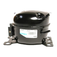
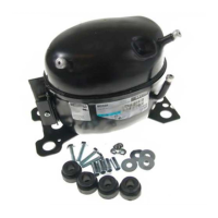
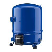
COMP Compressor
PTC Crankcase heater
IOL Internal overload line break
Three phase electrical
characteristics
Compressor
model
LRA
(Locked Rotor Amp)
A
MCC
(Maximum Continuous Current)
A
Winding resistance
(between phases +/- 7% at 25°C)
Ohm
349349349
NTZ048 32 16 22 10.1 4.8 5 2.80 11.55 13.10
NTZ068 48.5 25 29 14.8 8.4 8.5 1.58 7.11 9.70
NTZ096 72 32 20.4 10.1 1.20 5.03
NTZ108 72 45 57 21.4 12.1 11 1.20 4.00 2.54
NTZ136 97.2 51 64 29 14.3 15 0.98 3.80 2.54
NTZ215 147.7 74 110 42.3 22.3 23 0.57 2.23 1.26
NTZ271 198 96 150 56.5 27.0 30 0.41 1.61 0.84
 Loading...