Do you have a question about the Danfoss MCX15B2 and is the answer not in the manual?
Overview of the MCX15B2/MCX20B2 controller's capabilities, connectivity, and variants.
Details on plastic housing features, operating conditions, compliance standards (CE, UL), and warnings.
Key safety instructions for mounting, electrical connections, handling, and general operational precautions.
Specifications for power supply, analog inputs, digital inputs, and analog outputs.
Specifications for digital output relays, communication interfaces (CAN, RS485, Ethernet), and wire lengths.
Visual guide illustrating connection points for the controller's top and bottom boards.
Listing of connectors for top and bottom boards with their types and dimensions.
Physical dimensions of the controller and details on the LCD display and keyboard.
Lists of product part numbers and available accessory kits for the controller.
Instructions and considerations for replacing older MCX models with the MCX15B2/20B2.
Detailed connection diagrams for digital outputs and inputs when upgrading from MCX20B to MCX20B2.
Wiring diagrams for analog inputs and outputs for MCX20B to MCX20B2 upgrades.
Detailed connection diagrams for digital outputs and inputs when upgrading from MCX15B to MCX15B2.
Wiring diagrams for analog inputs and outputs for MCX15B to MCX15B2 upgrades.
Diagram for external relay connection when NC signals are required for specific outputs.
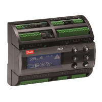
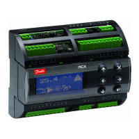
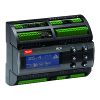
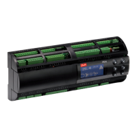
The Danfoss MCX15B2/20B2 is an advanced electronic controller designed to be at the forefront of the MCX range, offering extensive input/output capabilities, enhanced CPU performance, and robust connectivity. This controller integrates all the essential functionalities expected from MCX devices, including programmability, seamless connection to the CANbus local network, and up to two Modbus RS485 serial interfaces, each featuring galvanic isolation for reliable communication.
A key feature of the MCX15B2/20B2 is its ultra-wide range power supply, accommodating 24/110/230 V AC within a single product variant. This versatility simplifies installation and reduces the need for multiple power supply configurations. Connectivity is further enhanced by the inclusion of USB and Ethernet ports, enabling embedded Web server functionality and comprehensive IP protocols management. The controller is available in various models, offering options with or without a graphic LCD display and with either 15 or 20 digital outputs, allowing for tailored solutions to diverse application needs.
The device is built with a focus on durability and safety, featuring a plastic housing designed for DIN rail mounting in compliance with EN 60715. Its self-extinguishing properties meet IEC 60695-11-10 standards, and it passes the glowing/hot wire test at 960 °C according to IEC 60695-2-12. A ball test at 125 °C (IEC 60730-1) confirms its thermal resistance, while a leakage current of ≥ 250 V (IEC 60112) ensures electrical safety. The controller is designed for integration into Class I and/or II appliances, with an IP40 protection index on the front cover, making it suitable for environments with a pollution degree of 2. Its robust design ensures a long period of electric stress across insulating parts and a high category of resistance to heat and fire (Category D). Immunity against voltage surges is rated at category II or III for versions without a display, and the software is classified as Class A, indicating high reliability.
The MCX15B2/20B2 complies with essential EU standards, including the Low Voltage Directive (LVD 2014/35/EU) and the Electromagnetic Compatibility (EMC Directive 2014/30/EU). It adheres to EN 60730-1:2011 for automatic electrical control and EN 60730-2-9:2010 for temperature sensing controls. EMC compliance is ensured by meeting EN 61000-6-3:2007 +A1:2011 for residential, commercial, and light-industrial environments, and EN 61000-6-2:2005 for industrial environments. Furthermore, it is RoHS compliant (2011/65/EU and 2015/863/EU) and UL approved under file E31024, confirming its adherence to international safety and environmental regulations.
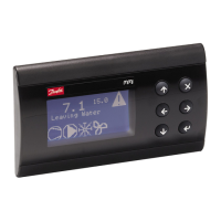
For maintenance and operation, the device features a user-friendly LCD display (if equipped) with an STN blue transmissive mode and a white LED backlight, both adjustable via software for optimal visibility. The display format is 128 x 64 dots, with an active visible area of 58 x 29 mm. The contrast is also software-adjustable. The keyboard consists of 6 keys, whose functions are defined by the application software. Display settings, including contrast and brightness, can be adjusted through a BIOS menu accessible by simultaneously pressing the Enter and X keys after power-on, allowing users to fine-tune the display for varying ambient conditions.
When replacing an older MCX15B-20B with an MCX15B2-20B2, the same application software can be used without modifications, and the universal power supply simplifies model selection. However, some wiring differences must be considered. The pinout may vary for certain inputs/outputs, and NC (Normally Closed) signals for relays DO10-DO13 are not available in the MCX15B2-20B2, requiring an external relay if these signals are needed. Alternatively, the application can be modified to utilize the additional NC14 signal of the MCX20B2. The analog outputs (AO) in the MCX15B2-20B2 are internally powered, so the L1 signal should not be connected. The 24 V DC power supply is not supported by the MCX15B2-20B2 (which operates on 40-230 V DC). Digital inputs are both contact-free and 24 V sensing, with internally connected DI common signals (DIC). It is crucial to ensure that DICs are connected to the same phase before replacement. A wiring kit, including specific cables and connectors, can be built to facilitate this replacement process, ensuring a smooth transition to the new controller.
General warnings emphasize that any use not described in the manual is unauthorized. Users must verify that installation and operating conditions, especially supply voltage and environmental factors, comply with the manual. As the device contains live electrical components, all service and maintenance must be performed by qualified personnel. The device is not intended for use as a safety device, and liability for injury or damage from incorrect use rests solely with the user.
Installation guidelines recommend vertical mounting and adherence to local standards and legislation. Electrical connections must only be made with the device disconnected from the main power supply. For safety, the appliance must be fitted inside an electrical panel without accessible live parts. The device should not be exposed to continuous water sprays, humidity above 90%, corrosive or pollutant gases, natural elements, explosive or flammable gas mixtures, dust, strong vibrations or shock, or rapid temperature fluctuations combined with high humidity that could cause condensation. Strong magnetic and/or radio interference should also be avoided. When connecting loads, the maximum current for each relay and connector must be observed. Suitable cable ends should be used, and screws tightened securely. Appropriate data communication cables, as specified in the "MCX hardware network specification" guide, should be used. Probe and digital input cables should be kept as short as possible, avoiding spiral paths around power devices and separating them from inductive loads and power cables to prevent electromagnetic noise. Electronic components on the board should not be touched to avoid electrostatic discharges. Finally, the product is not designed for direct exposure to the Internet.
| Type | Controller |
|---|---|
| Power Supply | 24V AC/DC |
| Digital Inputs | 6 |
| Analog Inputs | 2 |
| Relay Outputs | 2 |
| Analog Outputs | 1 |
| Communication | RS485 |
| Protocol | Modbus RTU |
| Enclosure Rating | IP20 |
| Protection Class | II |
| Housing Material | Plastic |
| Operating Temperature | -20 to +60 °C |