© Danfoss | DCS (vt) | 2020.10
AN320819413085en-000401 | 5
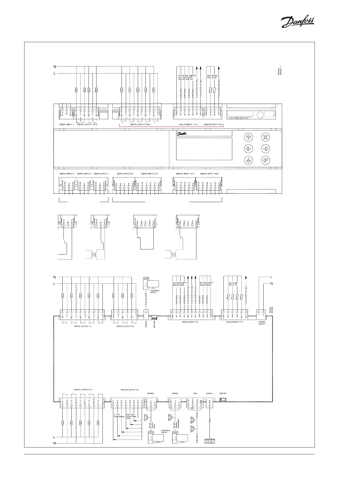
Connection diagram
24 V
SELV
24 V SELV
230 V or 24 V DIGITAL INPUT
(DI1 - DI4)
24 V230 VOR OR
N
N
L
N
L
24 VVOLTAGE FREE
VOLTAGE FREE or 24 V DIGITAL INPUT
(DI5 - DI22)
e.g. DIGITAL INPUT 5e.g. DIGITAL INPUT 1
MCX20B2 only
TOP BOARD
BOTTOM BOARD
*)
*)
NOTE: connection has to be made on the first and
last local network units, make the connection as
close as possible to the connector