Do you have a question about the Danfoss NovoCon Series and is the answer not in the manual?
Details the digital port for actuator connection and the requirement for common ground on the network.
Wiring details for the NovoCon digital cable, including power, ground, and signal wires.
Wiring details for the NovoCon analog cable, specifying power, ground, and analog input signals.
Identifies O-ring colors for Actuator NovoCon ChangeOver and ChangeOver Energy models.
Wiring details for the NovoCon Change Over Flexible cable, including control and feedback signals.
Wiring details for NovoCon Energy cables connecting to PT1000 surface and immersed sensors.
Wiring details for the NovoCon I/O cable, including power, ground, and input/output signal lines.
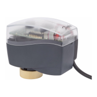
The Danfoss NovoCon® S CO6, Energy, I/O is a high-accuracy actuator designed for precise control in various HVAC applications. This device integrates multiple functionalities, including digital and analog control, energy monitoring, and flexible I/O options, making it a versatile component in building management systems.
The NovoCon® S actuator is engineered to provide accurate and reliable positioning of valves, ensuring optimal flow control and energy efficiency. It supports both digital and analog control signals, allowing for seamless integration into a wide range of control strategies. The "CO6" designation indicates its capability for specific control applications, while "Energy" highlights its integrated energy monitoring features, which can be crucial for optimizing system performance and identifying potential inefficiencies. The "I/O" aspect signifies its flexible input/output capabilities, enabling it to interact with various sensors and control devices within a network.
The actuator can be configured for different application modes, including digital control, analog control, and specific CO6 modes, with options for inverted CO6 mode. It supports various valve types, with a default setting for AB-QM DN 15 valves, and allows for the selection of design flow rates in both digital/analog and CO6 modes, including specific settings for heating and cooling applications.
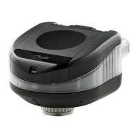
The NovoCon® S actuator is designed for ease of installation and configuration. It features a clear visual interface for calibration, including a button and LED indicators, as well as a DIP switch for various settings and a manual override wheel for local adjustments.
Connectivity is facilitated through digital ports that can accommodate different cables, such as CO6 actuator cables, Energy cables, I/O cables, analog cables, or voltage boosters. This modular approach allows for tailored installations based on specific application requirements.
Wiring diagrams are provided for various cable types:
The device features a DIP switch panel for configuration, allowing users to set MAC addresses (manually or automatically), terminate the last unit on a field bus, and select between BACnet MS/TP and Modbus RTU protocols. A power cycle is required when changing the communication protocol.
The serial number, which includes information like the device object instance number, can be easily removed from the actuator and added to installation drawings for documentation purposes.
Maintenance of the NovoCon® S actuator primarily involves ensuring proper installation and adherence to safety guidelines. The manual emphasizes the importance of qualified and authorized personnel for assembly, start-up, and maintenance work. It explicitly states that the power line must be switched off before wiring the actuator to prevent injury and damage.
For network configurations involving multiple AC power boosters, caution is advised when disconnecting transformers, as high voltage may persist on the primary side of disconnected power supplies due to the daisy-chain connection of NovoCons. It is recommended to disconnect both the primary and secondary sides of the transformer.
The device requires connection via a safety isolating transformer, and galvanic separations should be provided for segments crossing buildings to maintain electrical safety.
Disposal of the device should always follow local regulations, ensuring environmentally responsible end-of-life management. Regular checks of the wiring and connections, as per the provided diagrams, will help ensure continued reliable operation. The robust design, indicated by IP54/40 ratings, suggests a degree of protection against dust and water ingress, contributing to its durability in various operating environments.
| Power Supply | 24 V AC/DC |
|---|---|
| Control Signal | 0-10 V |
| Application | HVAC |
| Input Voltage | 24 V AC/DC |
| Communication Protocol | Modbus |