© Danfoss A/S (RA Marketing/MWA), Nov. 08 RS8FE102, 080R9278 23
OPTYMA
TM
Control three-phase Operation and Maintenance Guide
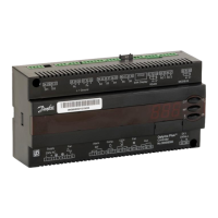
4. Remove the jumper from JUMPER JP2.
5. Alarm/AUX relay selection: Insert the jumper in
JUMPER JP2 in position 2-1 and set level 2
variable AU with the values 1, 2 or 5 according to
the desired function. Terminal blocks for free-
voltage contact on configurable relay are 16 and
17 on the electronic card.
Alarm/AUX relay Selection
6. If Alarm/Aux relay is used, wire directly on the
electronic card clamps. It is advisable to route that
wiring beside the connection cables from
electronic card and the housing back panel.