3.5.3 3-4* Ramp 1
Congure the ramp times for each of the 2 ramps
(parameter group 3-4* Ramp 1 and parameter group 3-5*
Ramp 2).
t
acc
t
dec
130BA169.11
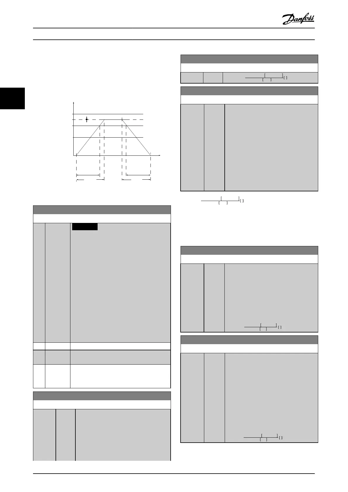
P 3-*2
Ramp (X)
Down
Time (Dec)
P 4-13
High-limit
RPM
Reference
P 1-25
Motor
speed
P 4-11
Low limit
Time
P 3-*1
Ramp (X)Up
Time (Acc)
Illustration 3.20 Ramp 1
3-40 Ramp 1 Type
Option: Function:
NOTICE
If [1] S-ramp Const Jerk is selected and
the reference during ramping is changed,
the ramp time may be prolonged to
realise a jerk-free movement, which may
result in a longer start or stop time.
Additional adjustment of the S-ramp
ratios or switching initiators may be
necessary.
Select the ramp type, depending on
requirements for acceleration/deceleration.
A linear ramp gives constant acceleration
during ramping. An S-ramp gives non-linear
acceleration, compensating for jerk in the
application.
[0] * Linear
[1] S-ramp
Const Jerk
Acceleration with lowest possible jerk.
[2] S-ramp
Const
Time
S-ramp based on the values set in 3-41 Ramp 1
Ramp Up Time and 3-42 Ramp 1 Ramp Down
Time.
3-41 Ramp 1 Ramp Up Time
Range: Function:
Size
related*
[ 1.00
- 3600
s]
Enter the ramp-up time, i.e. the acceleration
time from 0 RPM to parameter 1-25 Motor
Nominal Speed. Select a ramp-up time such
that the output current does not exceed the
current limit in parameter 4-18 Current Limit
during ramping. See ramp-down time in
parameter 3-42 Ramp 1 Ramp Down Time.
3-41 Ramp 1 Ramp Up Time
Range: Function:
par . 3 − 41 =
tacc × nnom par . 1 − 25
ref RPM
s
3-42 Ramp 1 Ramp Down Time
Range: Function:
Size
related*
[ 1.00 -
3600 s]
Enter the ramp-down time, i.e. the
deceleration time from
parameter 1-25 Motor Nominal Speed to 0
RPM. Select a ramp-down time preventing
overvoltage from arising in the inverter due
to regenerative operation of the motor. The
ramp-down time should also be long
enough to prevent that the generated
current exceeds the current limit set in
parameter 4-18 Current Limit. See ramp-up
time in parameter 3-41 Ramp 1 Ramp Up
Time.
par . 3 − 42 =
tdec × nnom par . 1 − 25
ref RPM
s
3.5.4
3-5* Ramp 2
To select ramp parameters, see parameter group 3-4* Ramp
1.
3-51 Ramp 2 Ramp Up Time
Range: Function:
Size
related*
[ 1.00 -
3600 s]
Enter the ramp-up time, that is the
acceleration time from 0 RPM to
parameter 1-25 Motor Nominal Speed. Select
a ramp-up time such that the output
current does not exceed the current limit in
parameter 4-18 Current Limit during ramping.
See ramp-down time in
parameter 3-52 Ramp 2 Ramp Down Time.
par . 3 − 51 =
tacc × nnom par . 1 − 25
ref rpm
s
3-52 Ramp 2 Ramp Down Time
Range: Function:
Size
related*
[ 1.00 -
3600 s]
Enter the ramp-down time, i.e. the
deceleration time from
parameter 1-25 Motor Nominal Speed to 0
RPM. Select a ramp-down time such that no
overvoltage arises in the inverter due to
regenerative operation of the motor, and
such that the generated current does not
exceed the current limit set in
parameter 4-18 Current Limit. See ramp-up
time in parameter 3-51 Ramp 2 Ramp Up
Time.
par . 3 − 52 =
tdec × nnom par . 1 − 25
ref rpm
s
Parameter Descriptions
VLT
®
HVAC Drive FC 102
62 Danfoss A/S © 03/2015 All rights reserved. MG11CE02
33
 Loading...


